Constant temperature method for storage battery

A battery, constant temperature technology, applied in secondary batteries, temperature control without auxiliary power supply, circuits, etc., can solve the problems of low reliability, large power consumption, and poor power supply conditions that cannot meet the needs of use.

Inactive Publication Date: 2009-09-16
耿直
View PDF0 Cites 12 Cited by
  • Summary
  • Abstract
  • Description
  • Claims
  • Application Information

AI Technical Summary

Problems solved by technology

[0002] In current storage battery applications, air conditioning equipment is usually used to control and adjust the working environment temperature of the storage batt...

Method used


Image

  • Constant temperature method for storage battery

Examples


Embodiment Construction

[0014] The embodiments of the present invention will be described below with reference to the accompanying drawings as an example.

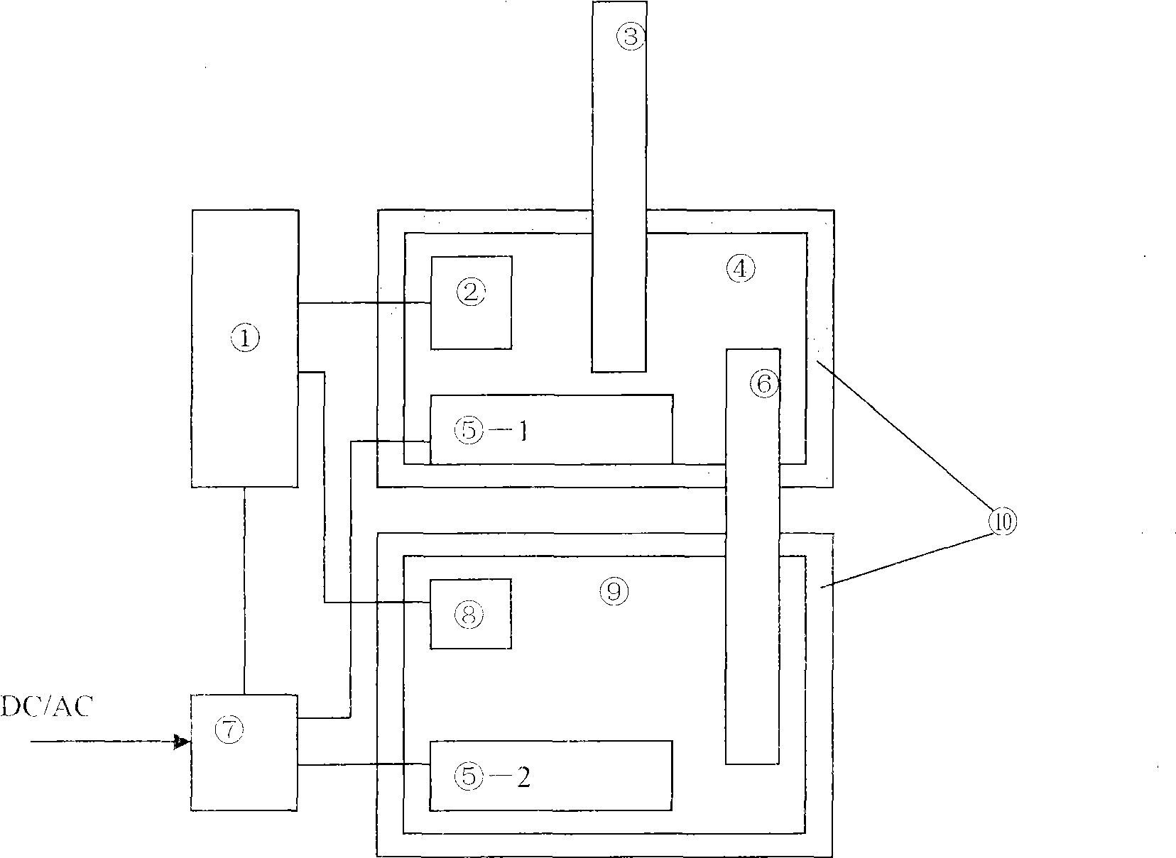
[0015] As shown in the attached figure, in which:

[0016] ① It is a temperature monitoring and control module, which is realized by PIC series single-chip microprocessor system;

[0017] ②, ⑧ are temperature sensors: use the digital temperature sensor chip AD7416, and connect with the temperature monitoring control module;

[0018] ③, ⑥ are the heating heat pipe and the cooling heat pipe respectively, and the two-phase closed thermosiphon and the heat pipe with variable conduction characteristics can be used; the evaporation section of the cooling heat pipe is set in the battery constant temperature box, and the minimum evaporation of the cooling heat pipe evaporation section is The temperature value is selected as the highest temperature value that the battery thermostat box needs to maintain when the battery is working normally. For lead-acid...


PUM


Abstract

The invention discloses a constant temperature method for a storage battery, which comprises a temperature monitoring control module, an electric heater, a battery incubator, a heat accumulator, a heat pipe, and the like, and adopts the heat accumulator for supplying heat and the heat pipe for keeping constant temperature and conducting heat and adjusting the temperature of the battery incubator. The storage battery constant temperature method has the advantages of low energy consumption, high reliability, and can be used in occasions with bad electricity supply environment, and is also characterized by easy implementation and convenient use.

Description

technical field [0001] The invention relates to a battery constant temperature method composed of a temperature monitoring control module, an electric heater, a battery constant temperature box, a heat accumulator, a heat pipe, etc., and belongs to the field of temperature regulation. Background technique [0002] In current storage battery applications, air conditioners are usually used to control and adjust the working environment temperature of the storage battery. Although the effect is better, the power consumption is large and the reliability is not high, and it cannot be used in some occasions with poor power supply conditions. [0003] Therefore, it is necessary to design a battery constant temperature method with low energy consumption, high reliability, and adaptability to places with poor power supply conditions, so as to meet the demand for temperature regulation of the working environment of the battery. Contents of the invention [0004] The object of the pre...

Claims


Application Information

Patent Timeline
IPC IPC(8): H01M10/50G05D23/01H01M10/613H01M10/615H01M10/635H01M10/6552H01M10/659
CPCY02E60/12Y02E60/10
Inventor 耿直
Owner 耿直
Why Eureka
Try Eureka