Independent wheel suspension

A suspension device, independent wheel technology, applied in the direction of suspension, elastic suspension, vehicle parts, etc., can solve the problems of tire wear, loss of tire lateral force potential, etc., to achieve reduced tire wear, low cost of angle measurement, accurate numerical value Effect

Inactive Publication Date: 2009-09-16
ZF FRIEDRICHSHAFEN AG
View PDF3 Cites 2 Cited by
  • Summary
  • Abstract
  • Description
  • Claims
  • Application Information

AI Technical Summary

Problems solved by technology

However, this leads to unfavorable situations during the car's linear coasting, that is, when individual car wheels bounce on one side, for example when driving over uneven ground.
In addition, with such a double-tie-rod wheel suspension, an unpredictable tire wear occurs and this loses the valuable lateral force potential of the tire

Method used


Image

  • Independent wheel suspension
  • Independent wheel suspension
  • Independent wheel suspension

Examples


Embodiment Construction

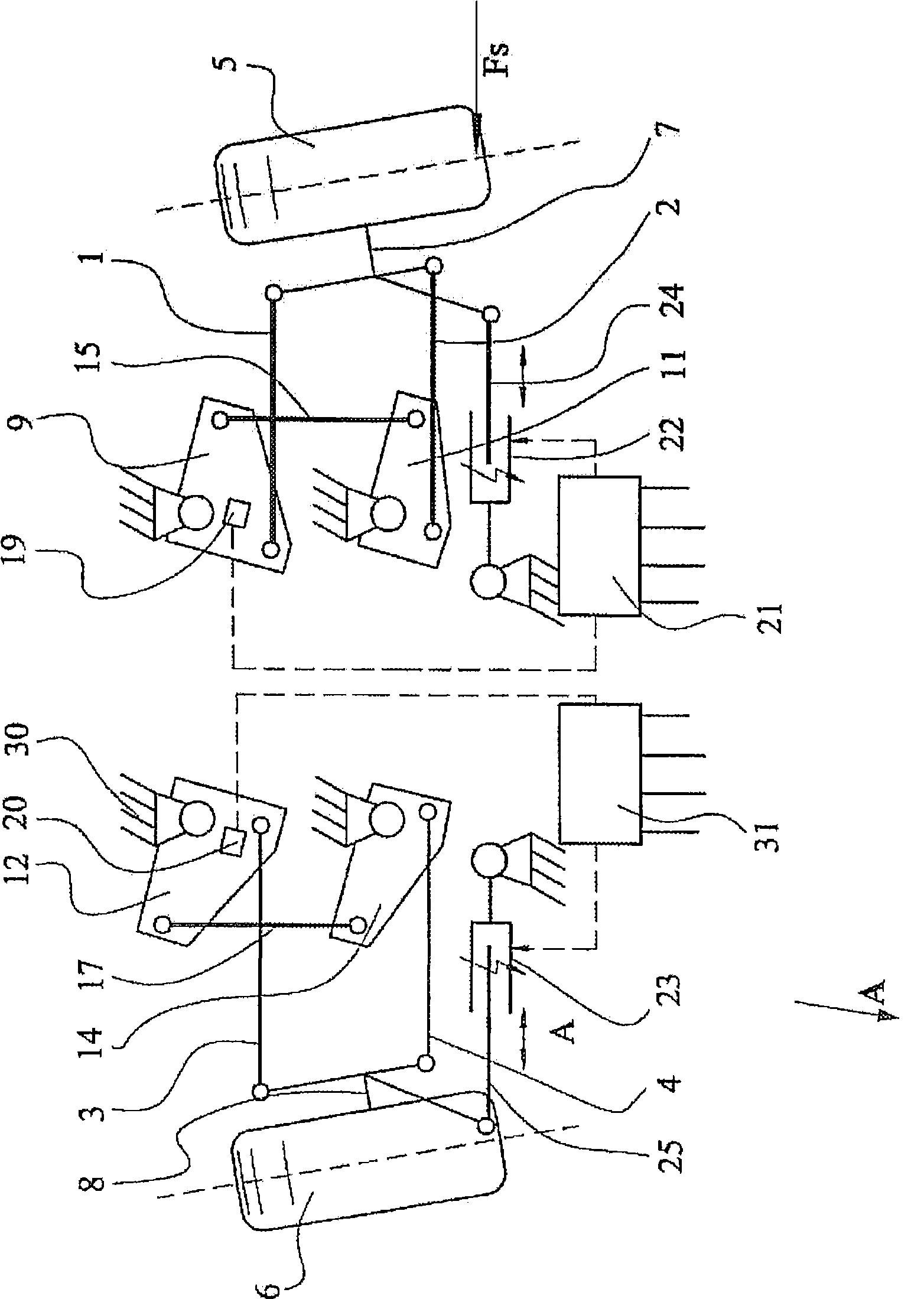
[0038] figure 1 A simplified first embodiment of the independent wheel suspension according to the invention is schematically shown, with the vehicle moving towards the observer. In the illustration, the wheel suspension is deflected due to a left turn. This means that the vehicle wheels 5 , 6 have an inclination relative to the vertical, which occurs, for example, when cornering. The steerable car wheels 5 and 6 are involved here. The independent wheel suspension has two guide rods 1 , 2 or 3 , 4 on each side with respect to the direction of travel indicated by the arrow “A”. Car wheel 5 is contained on the wheel support 7, and vehicle wheel 6 is contained on the wheel support 8. The two wheel carriers 7 or 8 are connected to the differential gear 9 , 11 or 12 , 14 via guide rods 1 , 2 or 3 , 4 respectively. The articulated connection between the vehicle wheels 5 , 6 and the differential 9 , 11 or 12 , 14 allows the deflection of the vehicle wheels 5 , 6 to be transmitted...


PUM


Abstract

Proposed is an independent wheel suspension for a motor vehicle, in which at least one first and at least one second link (1, 2, 3, 4) are in each case articulatedly coupled to a wheel carrier (7, 8) which supports a vehicle wheel (5, 6). The independent wheel suspension has compensating means (9, 10, 11, 12, 13, 14) for correcting wheel positions, wherein at least the first and the second link (1, 2, 3, 4) have a compensating means (9, 10, 11, 12, 13, 14) or are connected to a compensating means (9, 10, 11, 12, 13, 14), and at least two compensating means (9, 10 and 12, 13 respectively) of one wheel are connected to one another by means of at least one coupling element (15, 16, 17, 18). According to the invention, a wheel position of at least one of the vehicle wheels (5, 6) which differs from the neutral position can be sensed by means of a sensor unit (19, 20), composed of a measured value emitter and a measured value pick-up, which is arranged on at least one of the compensating means (9, 10, 11, 12, 13, 14) of the respective vehicle wheel (5, 6) or which is assigned to at least one of the compensating means (9, 10, 11, 12, 13, 14).

Description

[0001] illustrate technical field [0002] The invention relates to an independent wheel suspension according to the preamble of claim 1 . Background technique [0003] Due to increased safety and comfort requirements, interfering factors to the wheel suspension must be compensated better and better in smaller and smaller time units. The inclination of the wheels of the vehicle relative to the road surface is then also changed, for example by influence of lateral forces and swaying of the vehicle structure. The camber adjusted on the vehicle wheel leads to a change in the tire bearing area, so that the vehicle wheel loses its valuable grip on the ground. [0004] The hitherto known double tie-rod axles compensate the inclination to the wheel camber by purposefully influencing the wheel alignment by generating an oppositely directed negative camber which, for example, can be achieved when cornering. This is achieved by different lengths or orientations of the tie rods. How...

Claims


Application Information

Patent Timeline
Patent Type & Authority Applications(China)
IPC IPC(8): B60G3/26B60G7/00
CPCB60G2204/421B60G2400/05142B60G2204/143B60G2204/11B60G2200/462B60G7/006B60G3/26B60G2204/62B60G2200/46B60G7/00
Inventor F·霍伊斯勒S·阿拉马K·海德西克
Owner ZF FRIEDRICHSHAFEN AG
Why Eureka
Try Eureka