
Fuel cell system, method for controlling the fuel cell system, and mobile object

A fuel cell system and fuel cell technology, applied in the direction of fuel cells, fuel cell applications, fuel cell integration, etc., can solve the problems of increased output power of fuel cells, overcharging of storage devices, etc.

Active Publication Date: 2009-09-16
TOYOTA JIDOSHA KK
View PDF2 Cites 2 Cited by
  • Summary
  • Abstract
  • Description
  • Claims
  • Application Information

AI Technical Summary

Problems solved by technology

When the oxidizing gas supply is restarted in a state in which the output voltage of the fuel cell is lower than the standby voltage, the output power of the fuel cell increases rapidly, sometimes causing an electric storage device such as a secondary battery to be overcharged

Method used


Image

  • Fuel cell system, method for controlling the fuel cell system, and mobile object
  • Fuel cell system, method for controlling the fuel cell system, and mobile object
  • Fuel cell system, method for controlling the fuel cell system, and mobile object

Examples


Embodiment 1

[0048] Embodiment 1 relates to an example of a method for controlling a fuel cell system in a case where lapse of a predetermined time is adopted as an oxidizing gas supply condition.

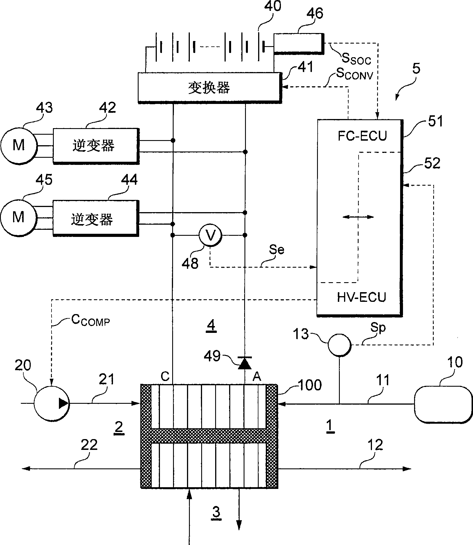
[0049] figure 2 is a block diagram illustrating the overall configuration of the fuel cell system of the embodiment of the present invention.

[0050] Such as figure 2 As shown, the fuel cell system of Embodiment 1 is composed of the following anode gas supply system 1 for supplying hydrogen as an anode gas to the fuel cell 100, a cathode gas supply system 2 for supplying air as a cathode gas to the fuel cell 100, and a power system 4 and a control unit 5 (control means) that performs the necessary control for the activation of the catalyst layer according to the present invention constitutes.

[0051] The fuel cell 100 has a stack structure in which a plurality of cells (unit cells) are stacked. Each battery has a structure in which a power generating body called MEA (Membrane Electrode A...

Embodiment 2

[0100] In Embodiment 1, the control unit 5 detects the processing time by actuating the timer, but in Embodiment 2, detects the processing time by detecting the actual output voltage of the fuel cell.

[0101] In the system configuration in embodiment 2 and figure 2 The system configuration of Embodiment 1 shown is the same.

[0102] Figure 6 is a flowchart illustrating the operation of the control unit 5 in the catalytic fuel cell system of Embodiment 2 of the present invention, which focuses on the catalyst layer regeneration process. As a prelude to the operation in Embodiment 2, it is assumed that the control unit 5 periodically monitors the output voltage of the fuel cell 100 (the secondary side voltage of the inverter 41 ) detected by the voltage sensor 48 . The same processing as that of Embodiment 1 is assigned the same step number below.

[0103] Such as Figure 6 As shown, in step S1, the control unit 5 continues to maintain the command signal C indicating the ...


PUM


Abstract

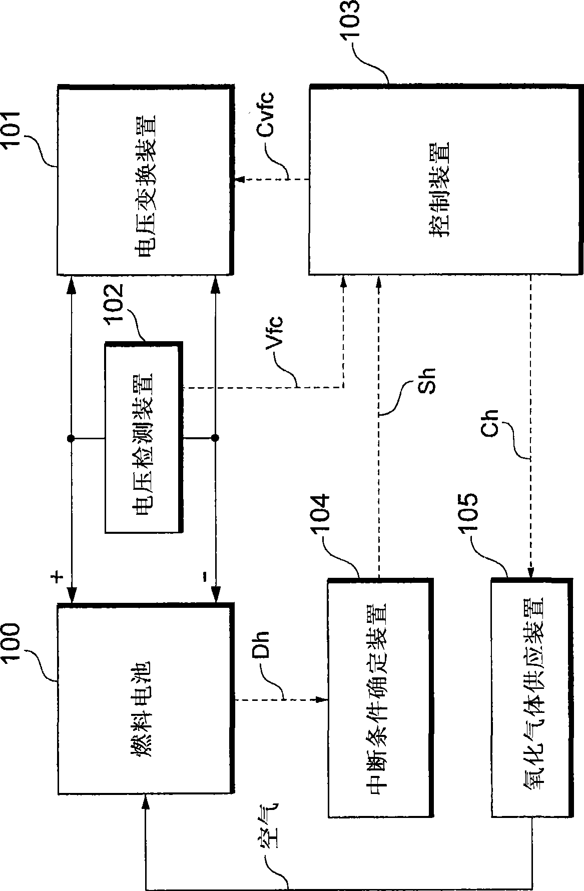
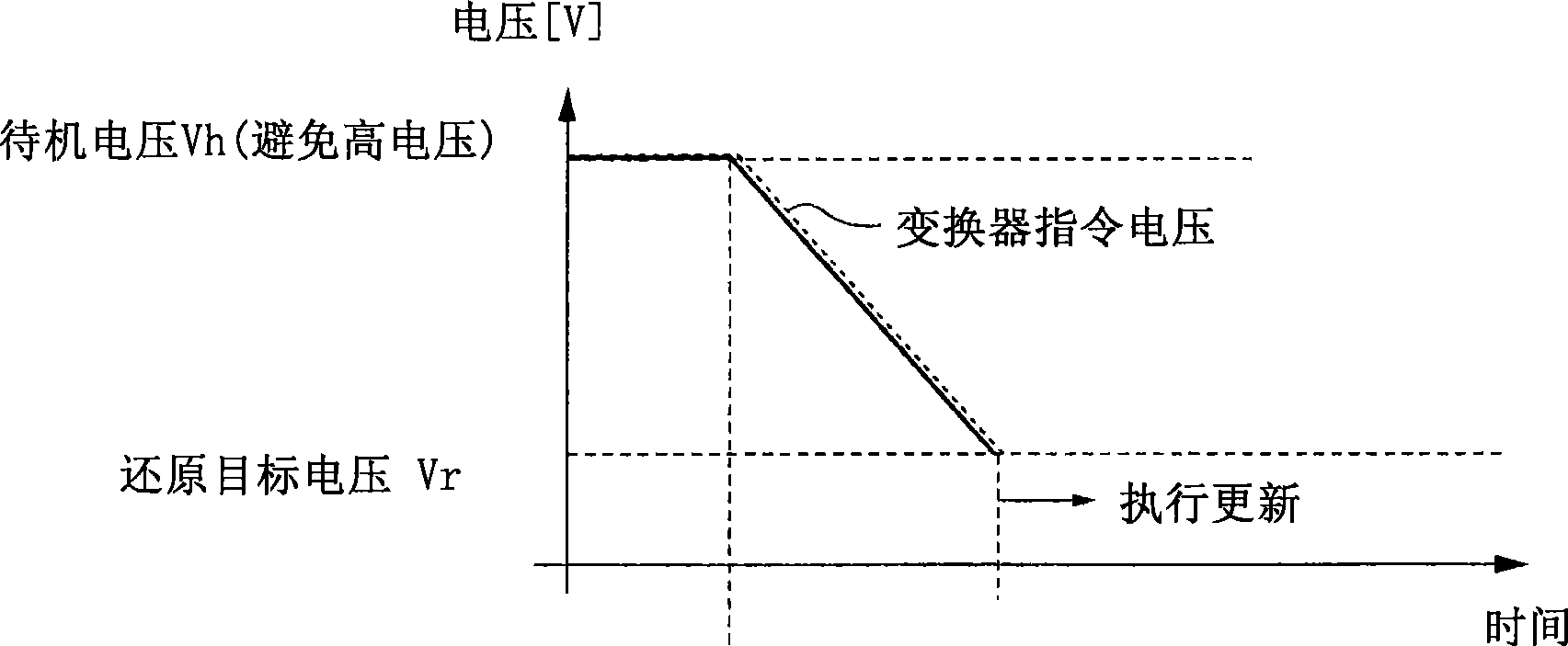
In catalyst activation treatment, the supply of oxidation gas is stopped, and the output voltage of a fuel cell (100) is linearly dropped toward a reduction target voltage. When activation treatment discontinuation conditions are met, the voltage instruction value of a converter (41) is returned to a standby voltage. When the output voltage of the fuel cell (100) is recovered to a value around the standby voltage, a compressor (20) is operated to start the supply of oxidation gas, and the catalyst activation treatment is terminated. According to the above constitution, the output power of the fuel cell (100) rapidly rises, and overcharge of a battery (40) can be avoided.

Description

technical field [0001] The present invention relates to a fuel cell system, and more particularly, to a technique for controlling a fuel cell system capable of reliably interrupting an activation process of a catalyst layer of a fuel cell while avoiding overcharging of an electric storage device. Background technique [0002] In a fuel cell system, the output voltage of the fuel cell decreases as oxygen is absorbed by the catalyst layer of the fuel cell during operation of the system. In this case, a process by which the supply of oxygen to the fuel cell is temporarily stopped and the output voltage of the fuel cell is lowered to the reduction region of the catalyst layer is conventionally performed, thereby affecting the catalyst layer of the fuel cell stack. Activation is performed (ie, reduction processing is performed). [0003] In the initial step of this activation process, the supply of oxidizing gas (for example, air) is stopped and then control is performed to lowe...

Claims


Application Information

Patent Timeline
IPC IPC(8): H01M8/04H01M8/00
CPCH01M8/04559H01M2250/402H01M8/0488H01M8/04089Y02E60/50H01M8/04753H01M8/04388Y02B90/12Y02B90/10Y02E60/10H01M8/04H01M10/44B60L50/50
Inventor 吉田道雄
Owner TOYOTA JIDOSHA KK
Learn More