Permanent magnet synchronous motor and enclosed compressor
A permanent magnet and synchronous motor technology, applied to synchronous motors with stationary armature and rotating magnets, magnetic circuit shape/style/structure, magnetic circuit, etc., can solve the problem of ineffective use of permanent magnet flux and low efficiency and other problems, to achieve the effect of low noise, low vibration and vibration suppression
- Summary
- Abstract
- Description
- Claims
- Application Information
AI Technical Summary
Problems solved by technology
Method used
Image
Examples
Embodiment approach 1
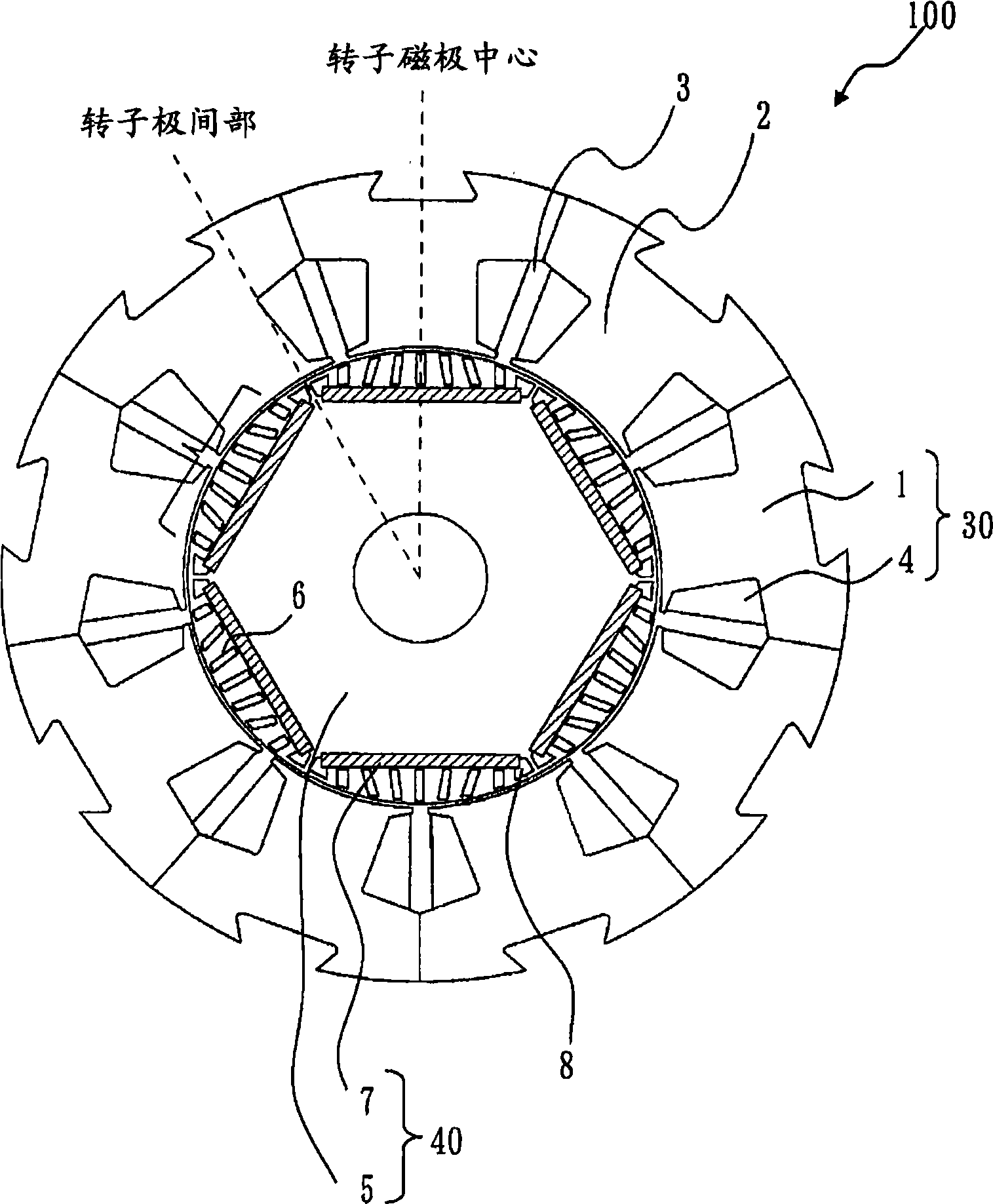
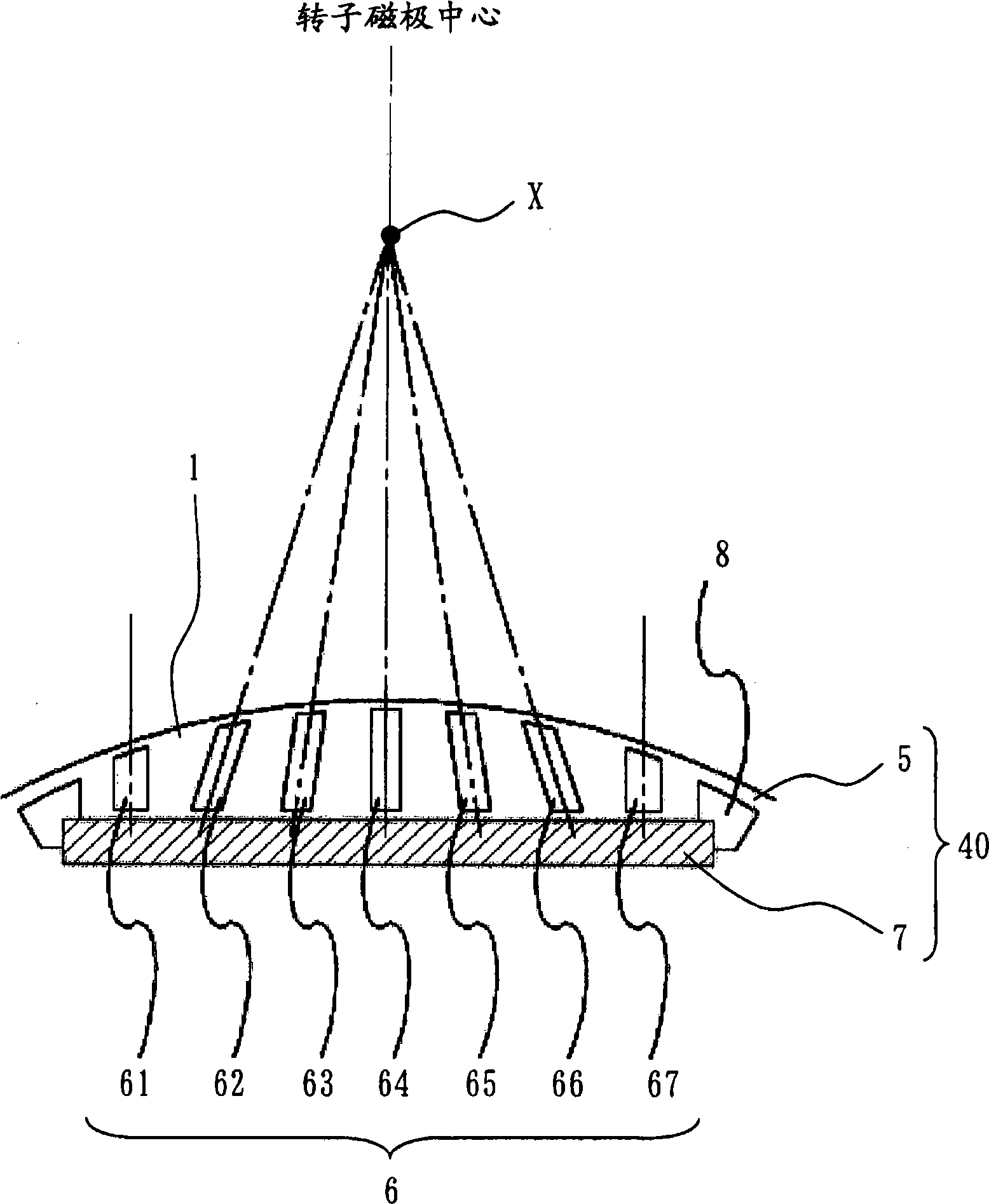
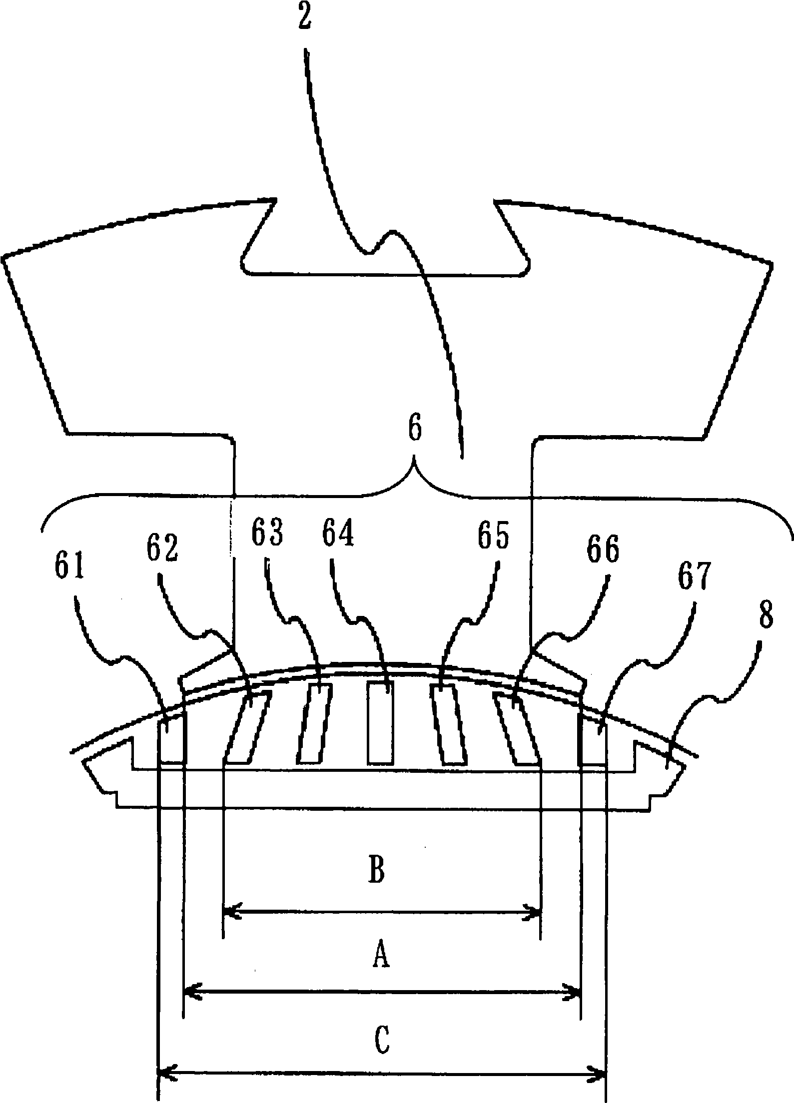
[0058] Figure 1 to Figure 3 is a diagram showing Embodiment 1, figure 1 is a cross-sectional view of the permanent magnet synchronous motor 100, figure 2 is a diagram showing part of the rotor 40 of the permanent magnet synchronous motor 100, image 3 It is a diagram showing part of the stator 30 and the rotor 40 of the permanent magnet synchronous motor 100 .
[0059] exist figure 1 Among them, the permanent magnet synchronous motor 100 includes a stator 30 and a rotor 40 . The stator 30 has a stator core 1 and a stator winding 4 . The stator core 1 is provided with nine slots 3 extending axially near the inner peripheral surface. The stator core 1 is formed by laminating a plurality of electromagnetic steel sheets with a thickness of about 0.1 to 1 mm. Nine magnetic pole teeth 2 are formed between adjacent slots 3 . The magnetic pole tooth portion 2 has a substantially parallel shape from the outer peripheral side to the inner peripheral side, and both the outer per...
Embodiment approach 2
[0083] Figure 4 It is a figure which shows Embodiment 2, and is a figure which shows part of the rotor core 5 of the permanent magnet synchronous motor 100. FIG.
[0084] exist Figure 4 Here, the core portion on the outer peripheral side of the slit 67 near the interpole portion is used as the outer peripheral thin-walled portion 9 . The core portion between the slit 67 and the magnet insertion hole 8 is used as the inner peripheral thin portion 11 . The core portion on the outer peripheral side of the magnet insertion hole 8 in the vicinity of the interpole portion serves as the interpole outer peripheral thin portion 10 .
[0085] In this embodiment, when the width dimension (radial dimension) of the outer peripheral thin-walled portion 9 is D1, and the width dimension (radial dimension) of the interpolar outer peripheral thin-walled portion 10 is D2, the configuration is such that D1< D2. In Embodiment 1, the case where the shape of the slit 67 in the vicinity of the ...
Embodiment approach 3
[0093] Figure 5 It is a figure which shows Embodiment 3, and is a longitudinal cross-sectional view of the rotary compressor 20 (an example of a hermetic compressor). exist Figure 5 Among them, a motor element 21 and a compression element 23 are accommodated in a hermetic container 22 of a rotary compressor 20 . The permanent magnet synchronous motor 100 shown in Embodiment 1 or Embodiment 2 is used for the electric element 21 .
[0094] The suction pipe 24 is connected to an evaporator (not shown) of the refrigeration cycle, and guides the refrigerant to the compression element 23 . The discharge pipe 25 is connected to the condenser of the refrigeration cycle, and sends the high-pressure refrigerant in the closed container 22 to the refrigeration cycle.
[0095] When the permanent magnet synchronous motor 100 shown in Embodiment 1 or Embodiment 2 is mounted on the rotary compressor 20, since the mounted permanent magnet synchronous motor 100 has high efficiency, a high-...
PUM
 Abstract
Description
Claims
Application Information
 - R&D
- Intellectual Property
- Life Sciences
- Materials
- Tech Scout
- Unparalleled Data Quality
- Higher Quality Content
- 60% Fewer Hallucinations
Browse by: Latest US Patents, China's latest patents, Technical Efficacy Thesaurus, Application Domain, Technology Topic, Popular Technical Reports.
© 2025 PatSnap. All rights reserved.Legal|Privacy policy|Modern Slavery Act Transparency Statement|Sitemap|About US| Contact US: help@patsnap.com


