Cleaning device for paint spraying apparatus

A technology for cleaning and spraying heads, which is applied in the field of cleaning devices for painting equipment, which can solve the problems of reducing the possibility of maintenance fires and having no high-speed moving parts, etc.

Active Publication Date: 2009-09-23
菲利普·约瑟夫 +1
View PDF1 Cites 17 Cited by
  • Summary
  • Abstract
  • Description
  • Claims
  • Application Information

AI Technical Summary

Problems solved by technology

Furthermore, the invention has no high-speed moving parts
maintenance, and th

Method used


Image

  • Cleaning device for paint spraying apparatus
  • Cleaning device for paint spraying apparatus
  • Cleaning device for paint spraying apparatus

Examples


Embodiment Construction

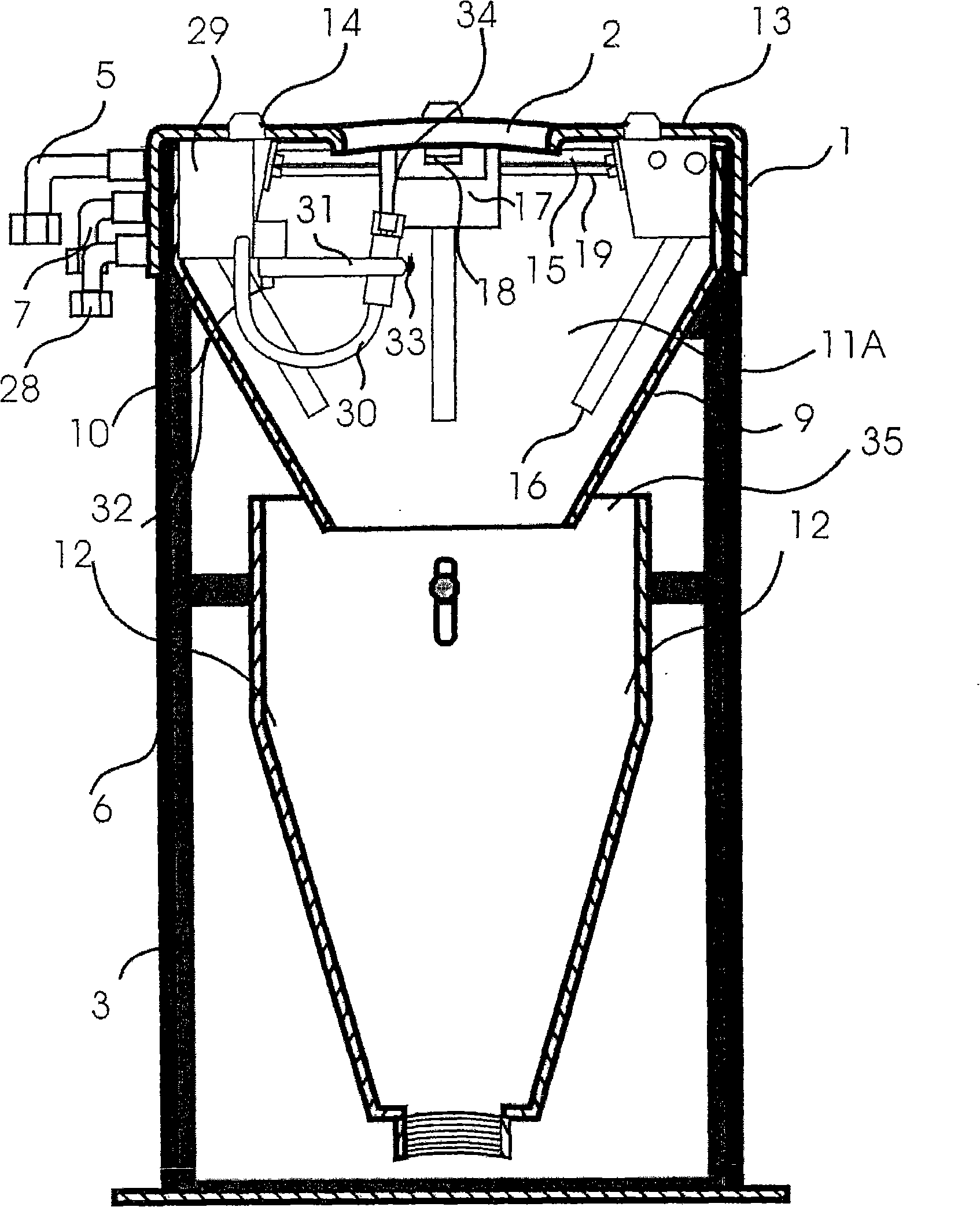
[0031] In one example of the present invention, a unique non-contact sealing system is included. Contained in this one-of-a-kind body: one solvent line with spray module head or multiple spray heads and check valve, one air line with air velocity acceleration circuit and evaporative drying circuit, one solvent with upward facing spray head and check valve Wire. This unique body is connected to a solvent recovery system.

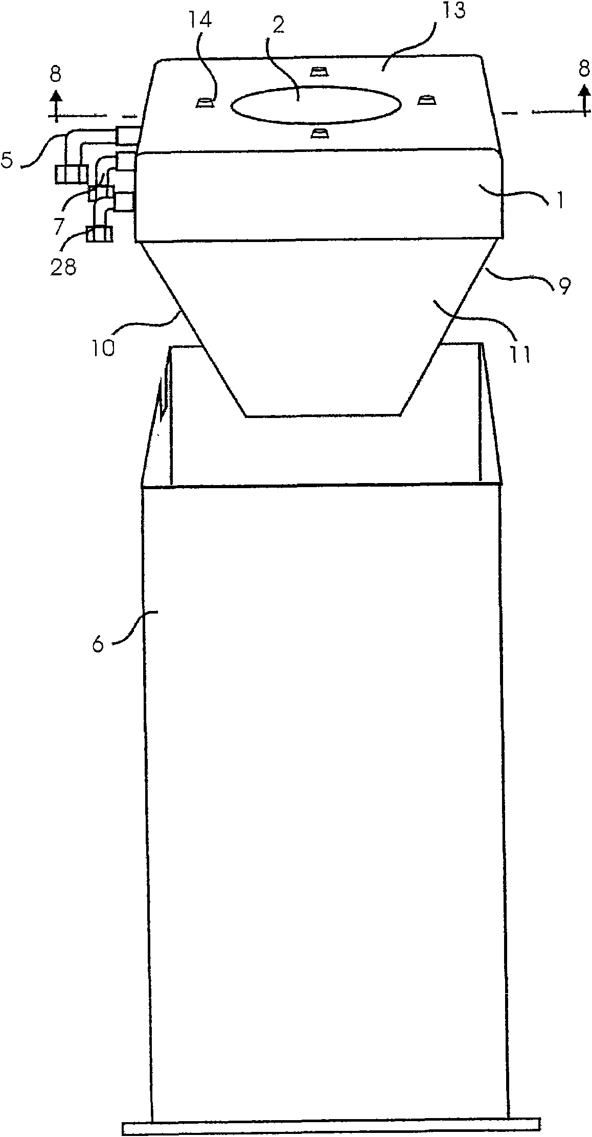
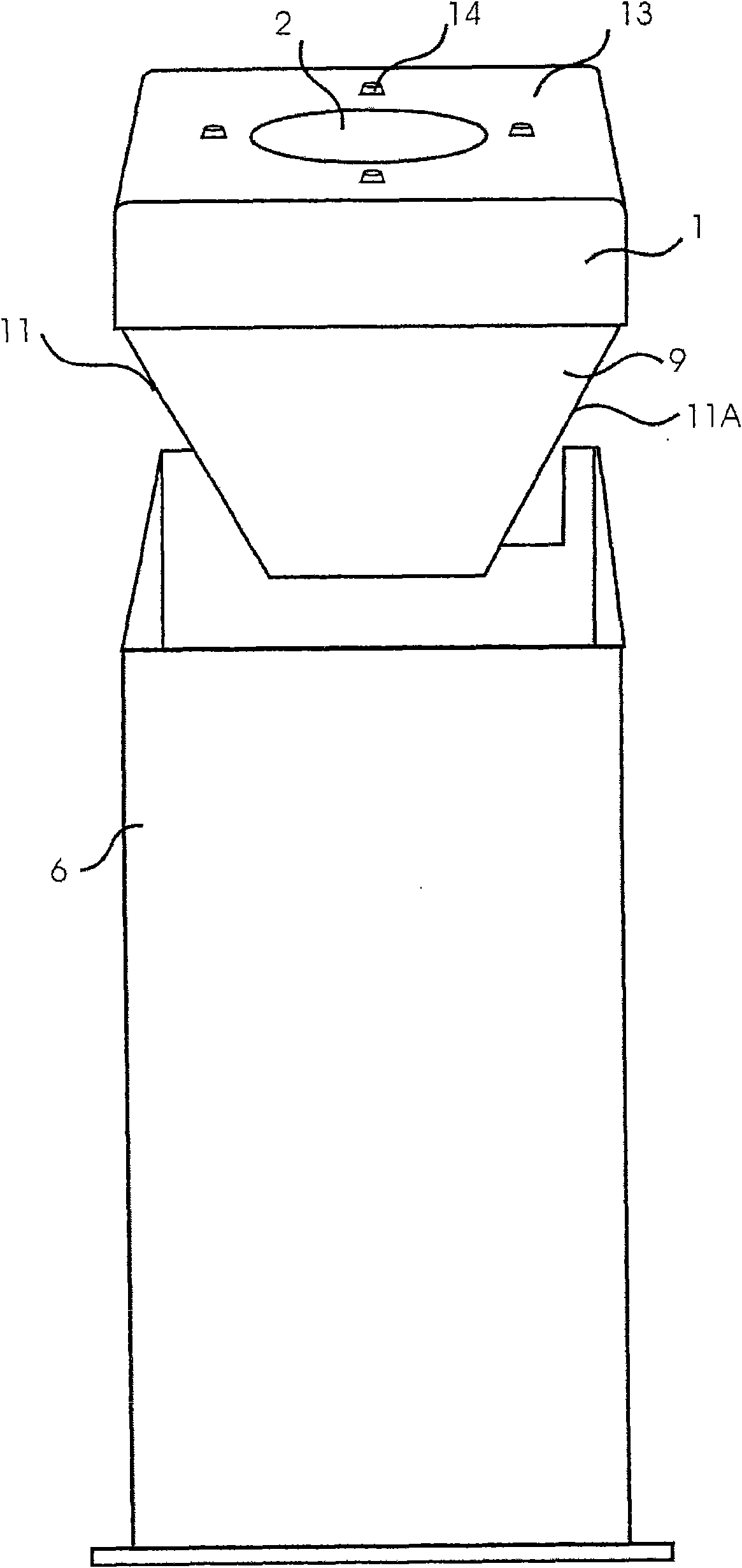
[0032] With reference to the accompanying drawings, and in particular to the Figure 1-3 , the spraying equipment cleaning device comprises a main body (generally indicated by reference numeral 1), manufactured as a monolithic piece of rigid material, preferably metallic rigid material. The main body is defined by a front wall 9 , a rear wall 10 , a pair of side walls 11 , a pair of solvent separators 12 and a top wall 13 . A non-contact sealing opening 2 is formed on the top wall. The main body is inserted into a holder 3 which is closed by a cover 6 . ...


PUM


Abstract

The invention relates to a device for drying a spray gun used in an automatic manufactory. The device is an effective two-stage solvent reclaiming system to lower cost in aspects of operation and environment. The device comprises a main body for accommodating a solvent spray head which is used for cleaning and inserted into the main body through non-contact seal, and an air spray head for cleaning an article once the article is cleaned. A low pressure area is generated in the main body by downwards guiding the air spray head so as to keep the air carried with a solvent in the main body. The air carried with the solvent is guided to a solvent separator positioned under the main body to reclaim the solvent.

Description

technical field [0001] The present invention relates to my invention "non-contact spraying equipment" disclosed in British Patent GB2413513 on January 24, 2007. Background technique [0002] The present invention generally relates to an industrial machine. More specifically, the present invention relates to, but is not limited to, an improvement in a non-contact spray painting device. Robotic painting industrial production line cleaning machine using solvent recovery system. [0003] The current method of cleaning spray equipment is to spray the solvent from the side perpendicular to the central axis of the applicator in a low pressure system or upwards in a sealed high pressure system. [0004] One problem with the prior art is that the applicator spray tip face or shroud is not properly cleaned. Surfaces and supply holes and shrouds are cleaned by adding a solvent line with one or more spray heads and one-way valves contained within a single container sprayed towards th...

Claims


Application Information

Patent Timeline
IPC IPC(8): B05B15/02B08B3/08
Inventor 菲利普·约瑟夫埃莉诺·约瑟夫
Owner 菲利普·约瑟夫
Why Eureka
Try Eureka