Probe vehicle wheel with variable diameter elastically capable of automatic extension

An automatic telescopic and detection vehicle technology, which is applied in the field of detection vehicle wheels, can solve the problems of weak obstacle-crossing ability and achieve the effects of improving obstacle-crossing ability, reducing grounding pressure, and increasing contact area

Active Publication Date: 2009-09-23
HARBIN INST OF TECH
View PDF0 Cites 37 Cited by
  • Summary
  • Abstract
  • Description
  • Claims
  • Application Information

AI Technical Summary

Problems solved by technology

[0005] The ability to overcome obstacles is not strong when walking on soft lunar slopes, and the collision between the wheels and hard objects will c

Method used


Image

  • Probe vehicle wheel with variable diameter elastically capable of automatic extension
  • Probe vehicle wheel with variable diameter elastically capable of automatic extension
  • Probe vehicle wheel with variable diameter elastically capable of automatic extension

Examples


specific Embodiment approach 1

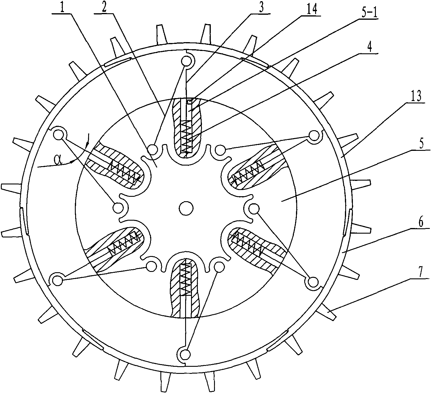
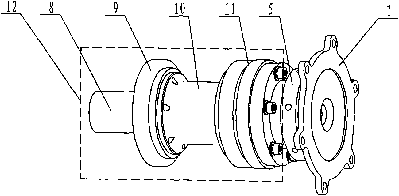
[0009] Specific implementation mode one: combine figure 1 with figure 2 Describe this embodiment, this embodiment includes driving flange 1, several support rods 2, several slide bars 3, several springs 4, support flange 5, several rim pieces 6, several tooth pieces 7, The driving device 12 and several limit blocks 14, the driving device 12 is composed of a driving motor 8, a suspension connecting flange 9, a motor sleeve 10 and a reducer 11, and the output end of the driving motor 8 passes through the suspension connecting flange 9 in turn The central hole of the motor sleeve 10 is connected to the input end of the reducer 11, the suspension connecting flange 9 is connected to the motor sleeve 10, the driving flange 1 is connected to the output end of the reducer 11, and the support flange 5 is set on the On the output shaft of the reducer 11 and located between the reducer 11 and the driving flange 1, several slide grooves 5-1 are arranged radially on the support flange 5,...

specific Embodiment approach 2

[0010] Specific implementation mode two: combination figure 1 To illustrate this embodiment, the number of support rods 2 , slide rods 3 , springs 4 , several rim pieces 6 and slide grooves 5 - 1 in this embodiment are the same, and they are evenly distributed along the circumference of the driving flange 1 . This design ensures that several unit structures of the wheel are the same, which is beneficial to the automatic deployment of the wheel. Other components and connections are the same as those in the first embodiment.

specific Embodiment approach 3

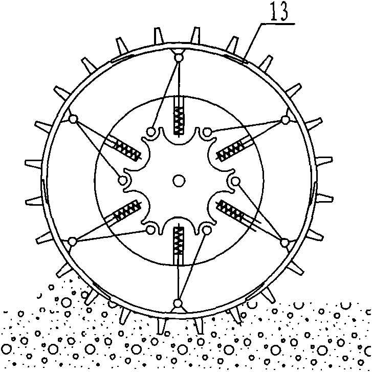
[0011] Specific implementation mode three: combination figure 1 with figure 2 To illustrate this embodiment, the angle α between the support rod 2 and the slide rod 3 in this embodiment is an acute angle, and the movement of the support rod 2 should be in a direction that reduces the angle α (increases the diameter of the wheel). This design enables the diameter of the wheel to expand and change freely, and the diameter of the wheel increases automatically when encountering obstacles. Other compositions and connections are the same as those in Embodiments 1 and 2.


PUM


Abstract

A probe vehicle wheel with variable diameter elastically capable of automatic extension relates to a probe car wheel. The invention solves the problem that the existing lunar vehicle has bad obstacle ability when meeting high barriers and traveling on loose and soft lunar slope as the wheel of the existing lunar vehicle is rigid wheel and the devices inside the wheel are impacted due to collision between the wheel and hard object. A driving flange is connected with the output end of a speed reducer in a driving device, the driving flange is hinged with a plurality of support bars, the other end of the support bar is hinged with a slide bar, one end of the slide bar is fixedly connected with the inside wall of a flange sheet, the other end of the slide bar is sleeved with a spring and is inserted in a corresponding sliding chute together with the spring, the slide bar can radially slide along the sliding chute, one end of the spring is fixedly connected with the slide bar, the other end of the spring is fixedly connected with the bottom of the sliding chute, a limited block is installed inside the sliding chute and positioned outside the spring, and a plurality of tooth sheets are uniformly distributed on the flange and are fixedly connected with the flange. In the invention, the wheel diameter can be adjusted automatically according to topographic condition, thereby improving wheel traveling ability and reducing the impact of wheel for the devices inside.

Description

technical field [0001] The invention relates to a detection vehicle wheel. Background technique [0002] Exploration vehicles used on planetary surfaces or other harsh environments require strong terrain adaptability and flexible steering capabilities. The rover wheel is one of the most critical components of the rover's mobile system. The configuration of the wheels has a critical impact on the driving ability of the lunar exploration vehicle and the ability to adapt to the lunar surface terrain. The wheels of the rover must be able to effectively reduce the ground pressure, that is, reduce the amount of sag of the wheels; and create necessary constraints on the flow of dust particles, resulting in greater traction. [0003] At present, the structure of the wheels of the exploration vehicle mostly adopts a rigid cylindrical wheel structure. When this kind of wheel walks on the surface of the moon on rocky obstacles and soft lunar slopes, the wheels will easily slip, and t...

Claims


Application Information

Patent Timeline
IPC IPC(8): B60B19/00B60B9/02B64G1/16
Inventor 邓宗全高海波张朋李所军
Owner HARBIN INST OF TECH
Why Eureka
Try Eureka