Image processing device, image processing method, and program
一种图像处理装置、帧图像的技术,应用在图像数据处理、图像增强、图像分析等方向,能够解决不能够期待得到事前信息等问题
- Summary
- Abstract
- Description
- Claims
- Application Information
AI Technical Summary
Problems solved by technology
Method used
Image

Examples
Embodiment approach 1
[0087] This embodiment is one of the modes in which the inclination is detected from the frame image data to be processed as a correction parameter, and image processing is performed on the frame image data to be processed using the correction parameter. This image processing includes rotational transformations.
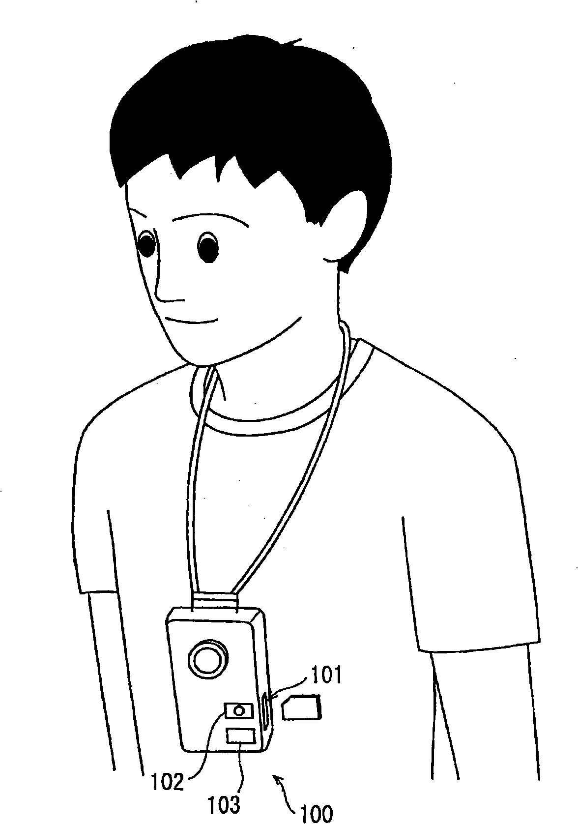
[0088] figure 1 It is a figure which shows the usage form of the imaging device to which the image processing apparatus of this invention is applied. As shown in the figure, a user can carry the video camera 100 incorporating the image processing device of the present invention on his or her body using a sling, and can perform photography based on hands-free photography techniques. The housing of the video camera 100 includes a card slot 101 for attaching and detaching a semiconductor memory card as a recording medium, a recording button 102 for accepting an operation to start shooting, and a stop button 103 for receiving an operation to stop shooting. By pressing ...
no. 2 Embodiment approach
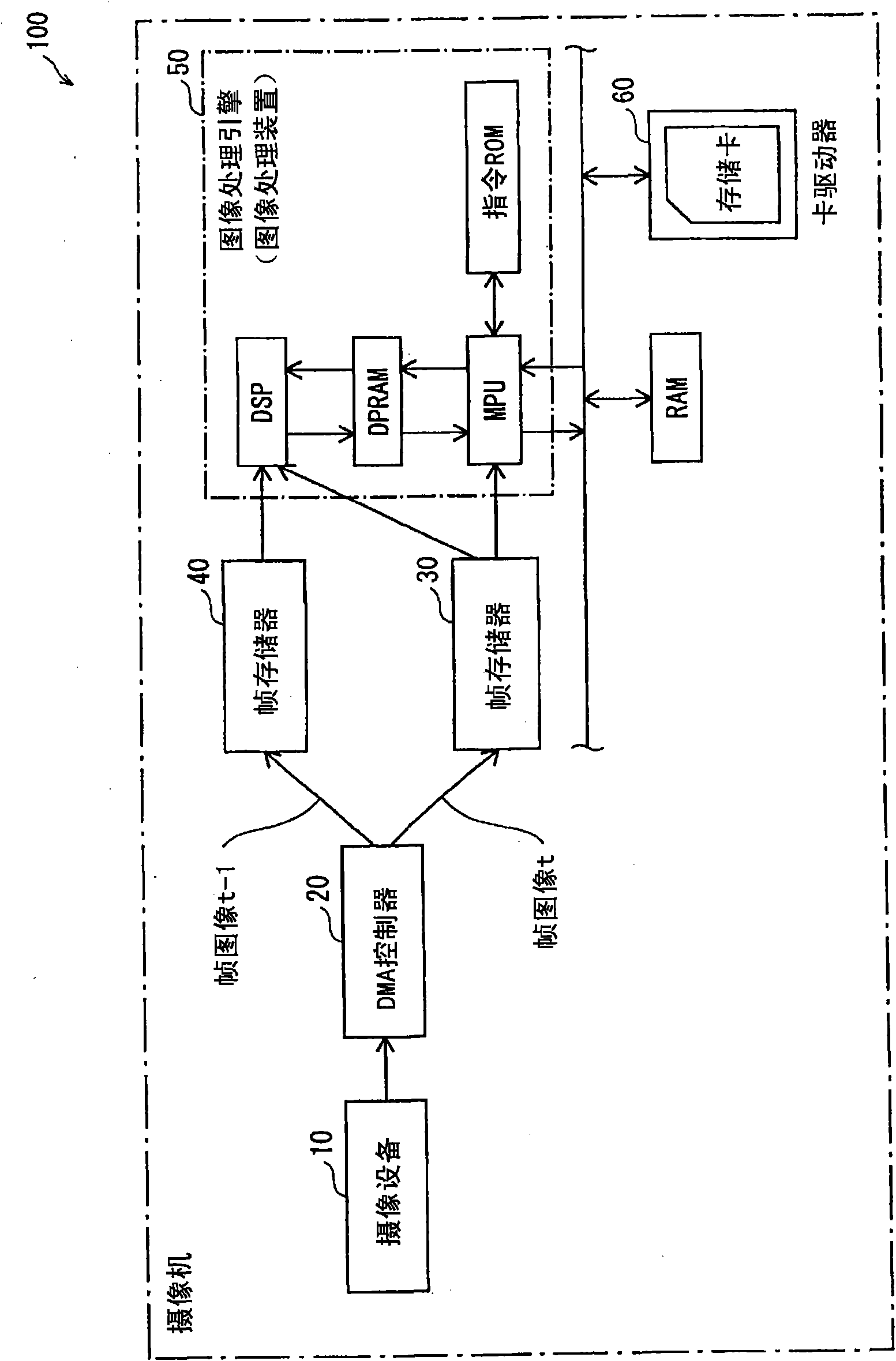
[0178] Figure 12 It is a diagram showing the hardware configuration of the image processing device according to the second embodiment of the present invention. exist Figure 11 in, right with figure 1 The same symbols are used for the same constituent elements, and explanations are omitted.
[0179] Such as Figure 11 As shown, the difference between the second embodiment of the present invention and the first embodiment is that an inertial sensor 70 capable of detecting an angular component in the roll axis direction is added, and the output from the sensor 70 is used by the line segment detection unit 2 . An acceleration sensor, a gyro sensor, etc. are mentioned as an inertial sensor which can detect the angular component of this roll axis direction.
[0180] The inertial sensor 70 acquires the angle in the roll axis direction at the time when the imaging device 10 captures the frame image t. The value at this time may be an original value output from the inertial sens...
no. 3 Embodiment approach
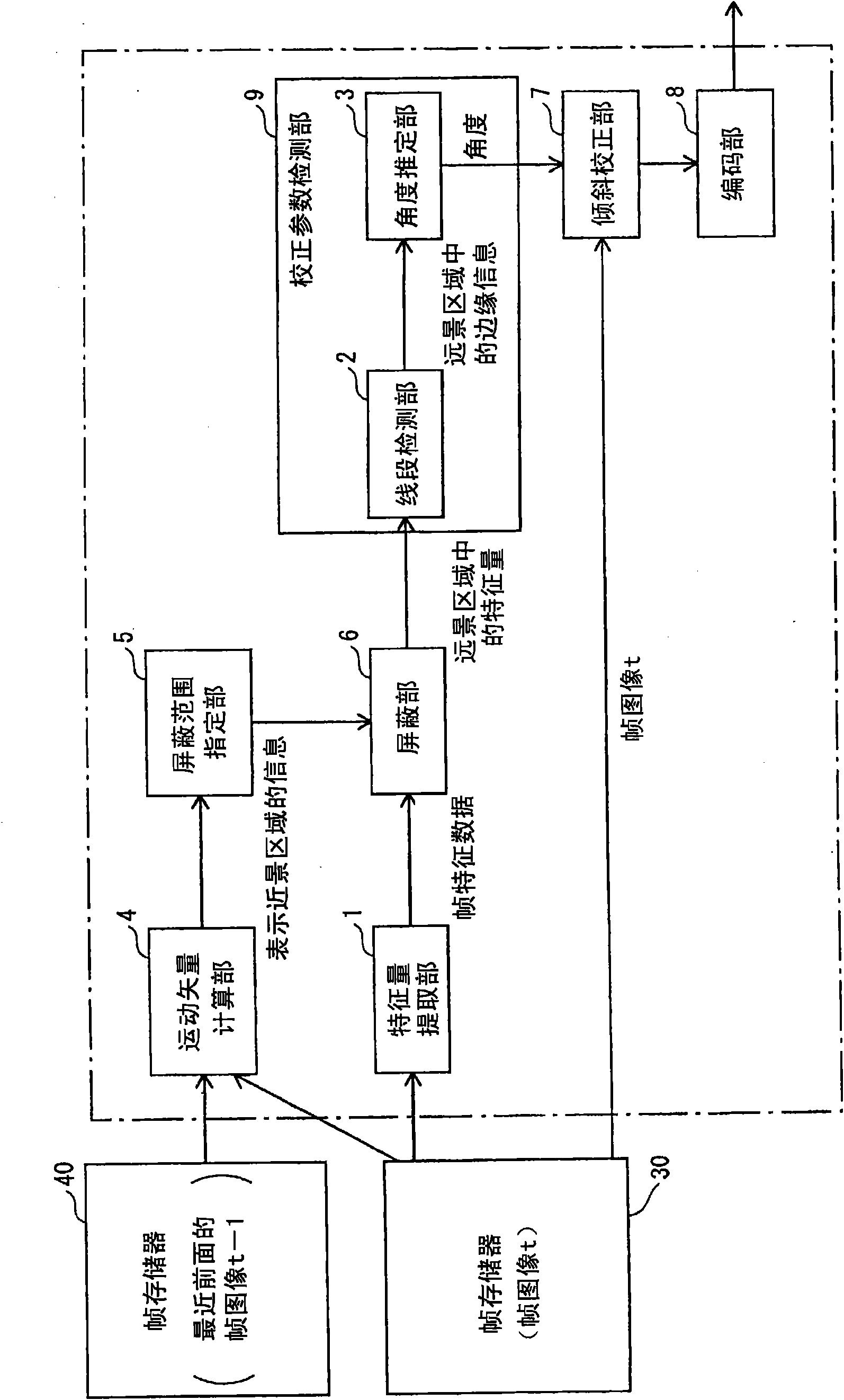
[0187] This embodiment is an improvement in the case where the coordinate system where the camera holder is located moves by itself. As in the case where the camera holder rides on a moving object such as a car, when the coordinate system where the camera holder is located moves by itself, the movement amount of the area where the structure exists may be relatively large. In this case, if the region used for tilt correction is determined only based on the magnitude of the motion vector as in the first embodiment, it may be misjudged that the region where the structure exists is the foreground region. The feature quantity of the region is used to obtain the inclination angle. In this case, it cannot be dealt with by the above-mentioned configuration in which the inclination angle is estimated from the background area.
[0188] Therefore, in the present embodiment, the histograms of degrees representing the range of angles existing in the image data are obtained for the distant...
PUM
 Abstract
Description
Claims
Application Information
 - R&D Engineer
- R&D Manager
- IP Professional
- Industry Leading Data Capabilities
- Powerful AI technology
- Patent DNA Extraction
Browse by: Latest US Patents, China's latest patents, Technical Efficacy Thesaurus, Application Domain, Technology Topic.
© 2024 PatSnap. All rights reserved.Legal|Privacy policy|Modern Slavery Act Transparency Statement|Sitemap