Minitype tiller gearbox

A technology for tillage machines and gear boxes, which is applied in the fields of tillage machines, agricultural machinery and tools, etc. It can solve the problems of long deceleration path, complex structure, and large power loss, etc., and achieve the reduction of the volume of the gear box, the simple structure of the speed change, and the Reasonable effect of variable speed structure

Inactive Publication Date: 2010-12-29
江苏恒昌农机科技有限公司
View PDF5 Cites 0 Cited by
  • Summary
  • Abstract
  • Description
  • Claims
  • Application Information

AI Technical Summary

Problems solved by technology

The disadvantages of this speed change method are: 1. The deceleration path is long, resulting in a large volume of the gearbox; 2. The deceleration path is long, the step-by-step deceleration structure is complicated, and the power loss is large; 3. Because the speed is finally transmitted to the driving shaft of the traveling mechanism and Before the power output shaft, it has been decelerated step by step, so the output power of the power output gear will be restricted by the gear coefficient ratio of the previous deceleration, so that the power of the supporting agricultural machinery is limited

Method used


Image

  • Minitype tiller gearbox
  • Minitype tiller gearbox
  • Minitype tiller gearbox

Examples


Embodiment Construction

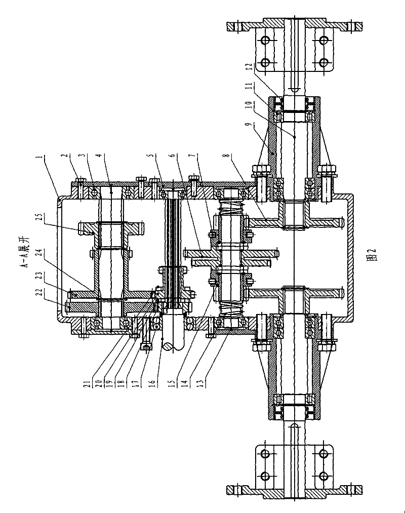
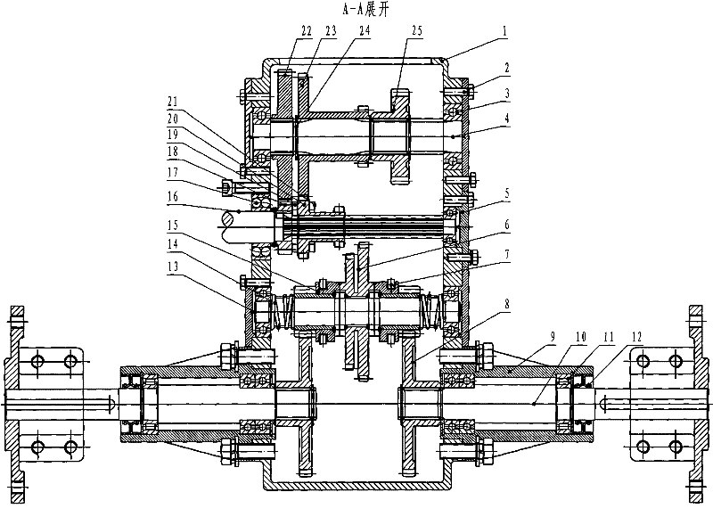
[0010] The input shaft 16 of the miniature cultivator gearbox is an integrally designed long shaft, a part of the long shaft is erected in the sprocket transmission box, and the other part is erected through the cylindrical hole self-aligning ball bearing 17 and the deep groove ball bearing 3 respectively. On the left and right side walls of the gearbox casing 1. The input shaft 16 protruding into the box body 1 is set on an involute spline, the main drive gear 18 is welded and fixed on the side of the input shaft 16 close to the chain transmission box, and the slip shifting dual gear 20 is set on the side with an involute On the input shaft part of the linear spline, an installation positioning spacer 19 is arranged between the main drive gear 18 and the sliding shifting double gear 20, and a shift fork 21 is arranged on the slip shifting double gear 20, and the shifting fork 21 toggles Sliding variable speed duplex gear 20 makes this gear box walking drive output be four gea...


PUM


Abstract

The invention provides a minitype tiller gearbox which relates to farm machinery, in particular to a transmission mechanism for a minitype tiller. The minitype tiller gearbox comprises a box body and a gear arranged on a shaft, wherein the shaft arranged on the box body comprises an input shaft, a power output shaft, an extension shaft and two travel driving shafts; wherein the portion of the input shaft extending into the box body is fixedly provided with a main driving gear and a slippage gearshift duplicate gear; the power output shaft is fixedly provided with a main driven gear and a power output gear; a reverse gear duplicate gear is sleeved on a shaft between the main driven gear and the power output gear; a duplicate adapter gear is fixedly arranged at the middle of the extension shaft; two adapter gears are respectively sleeved at the left and right sides of the duplicate adapter gears; a pressure spring is arranged at the outside of the adapter gear; and the part of the travel driving shaft extending into the box body is fixedly provided with a travel driving gear. The invention has the advantages of compact structure, little power consumption and reasonable design of thetransmission structure.

Description

technical field [0001] The invention relates to an agricultural machine, in particular to a transmission mechanism for a miniature cultivator. Background technique [0002] The speed change mode of the existing miniature cultivator gear box is: the rotating speed of the input shaft is first decelerated step by step through several gear pairs, and then the drive shaft and the power output shaft of the transmission traveling mechanism. The disadvantages of this speed change method are: 1. The deceleration path is long, resulting in a large volume of the gearbox; 2. The deceleration path is long, the step-by-step deceleration structure is complicated, and the power loss is large; 3. Because the speed is finally transmitted to the driving shaft of the traveling mechanism and The power output shaft has been decelerated step by step before, so the output power of the power output gear will be restricted by the gear coefficient ratio of the previous deceleration, so that the power ...

Claims


Application Information

Patent Timeline
Patent Type & Authority Patents(China)
IPC IPC(8): A01B33/08
Inventor 季顺中吴崇友高永福杨根林李群
Owner 江苏恒昌农机科技有限公司
Why Eureka
Try Eureka