Eureka AIR delivers breakthrough ideas for toughest innovation challenges, trusted by R&D personnel around the world.

Bionic detection and rescue system

A rescue head and power unit technology, applied in the field of detection and rescue systems, can solve problems such as difficulty in approaching quickly, narrowness, and irregular disaster paths, and achieve the effects of wide application range, convenient operation, and continuation of life

Inactive Publication Date: 2012-10-31
王彦明
View PDF5 Cites 1 Cited by
  • Summary
  • Abstract
  • Description
  • Claims
  • Application Information

AI Technical Summary

Problems solved by technology

When a disaster occurs, the disaster scene is often in a mess, and there is a possibility of a second disaster at any time. The route of the disaster is not only irregular, but also extremely narrow or dangerous with poison, electricity, fire, etc., and it is generally difficult for personnel to quickly approach and implement effective measures. rescue

Method used


Image

  • Bionic detection and rescue system
  • Bionic detection and rescue system
  • Bionic detection and rescue system

Examples


Embodiment 1

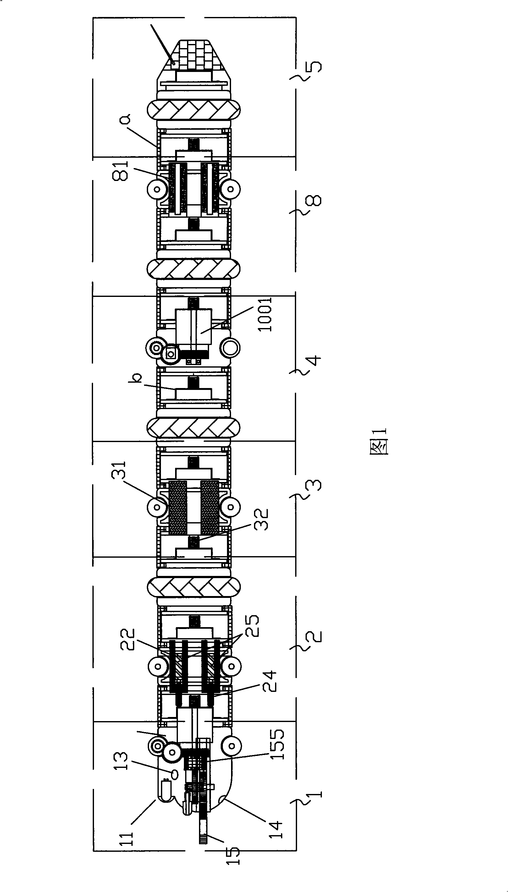
[0039] refer to figure 1 , which is a schematic diagram of the structure of this embodiment. A bionic detection and rescue system, which includes a detection and rescue head 1, a steering power unit body 2, a control device power unit body 3, a transmitting and receiving power unit body 5, and a multi-section motion unit body 4 connected in series through a spring body; The front end of the steering power unit body 2 is connected with the end of the detection rescue head 1, the end of the steering power unit body 2 is connected with the front end of the control device power unit body 3 through the movement unit body connecting spring 32, and the end of the control device power unit body 3 The end is connected with the front end of the moving unit body 4 to form a serpentine body, and the transmitting and receiving power unit body 5 is installed at the tail of the body.

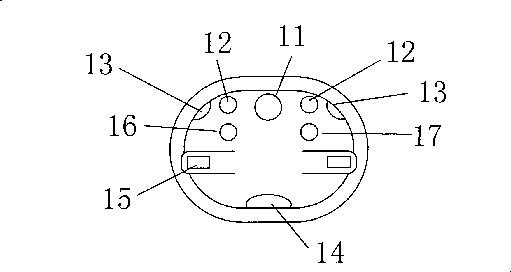
[0040] refer to figure 2 A video camera 11 and a lighting lamp 12 are installed on the front and upper e...

Embodiment 2

[0050] The difference between this embodiment and Embodiment 1 is:

[0051] refer to Figure 16 , in this embodiment, also includes handling control box 7, and this handling control box 7 comprises box body 71, carrying frame 72, storage battery 73, winch 74, earphone microphone 75, one-way motion controller 76, display 77, Control keyboard 78, storage battery 73 is installed in casing 71 right side bottoms, hoist drum 74 is installed in casing 71 central, and it is used for coiling up the system of the present invention, earphone microphone 75, display 77, control keyboard 78 all Installed on the top of the box body 71 and connected with the load control executive device of the control device power unit body 3, the one-way motion controller 76 is installed on the front bottom of the box body 71 and is also installed with a movement that can slide left and right at the front bottom of the box body 71. The unit body inlet and outlet 79, the liquid and air supply device is inst...


PUM


Abstract

The present invention discloses a bionic detection and rescue system, which comprises a detection and rescue head, a turning power unit, a control power unit, an transmitting / receiving power unit, and several segments of moving units connected serially by springs; wherein, the front-end of the turning power unit is connected with the tail end of the detection and rescue head, the tail end of the turning power unit is connected with the front-end of the control power unit, and the tail end of the control power unit is connected with the front-end of the first moving unit, so that a main body is formed; the transmitting / receiving power unit is mounted on the tail end of the main body. The present invention has high accessibility, can move flexibly, and is easy to operate.

Description

technical field [0001] The invention relates to a detection and rescue system, more specifically, to a bionic detection and rescue system. Background technique [0002] At present, although it is an era of peace, terrorism hangs over the people of the world like a lingering dark cloud with the occurrence of the 9 / 11 incident. Various extremist terrorist organizations and forces use means such as explosions, poisoning, and even biological and chemical weapons and sub-nuclear weapons to attack public places, causing a large number of civilian casualties, disturbing people's hearts, and disrupting social order. At present, the security situation in my country and its surrounding areas is very severe. The bold actions of various forces and repeated violent terrorist attacks have caused a large number of casualties and huge economic losses, disrupting social order. The 5.12 Wenchuan Earthquake ruthlessly destroyed the beautiful homes of millions of people and claimed nearly 100,...

Claims


Application Information

Patent Timeline
Patent Type & Authority Patents(China)
IPC IPC(8): A62B99/00B25J5/04B25J13/00B62D57/02B62D5/04
Inventor 王彦明
Owner 王彦明
Why Eureka
Eureka Blog
Learn More