Insert-fixing device of compaction forming die

A technology for fixing devices and forming molds, applied in the field of mold manufacturing, can solve the problems of falling into the mold cavity, loss of magnetism, inconvenient manufacturing and use, etc., and achieve the effect of improving friction and safe and reliable installation and fixing

Active Publication Date: 2011-01-19
无锡品源科技咨询有限公司
View PDF0 Cites 0 Cited by
  • Summary
  • Abstract
  • Description
  • Claims
  • Application Information

AI Technical Summary

Problems solved by technology

Hydraulic presses generally move up and down. When there are inserts in plastic products and the inserts inevitably appear in the direction of the upper mold of the mold, it is difficult to install the inserts before the mold is closed.
[0003] The insert fixed on the insert core will be affected by gravity when it is loaded into the mold, and may fall into the mold cavity, causing the mold to be crushed
In the prior art, in order to solve such problems, some magnets are placed on the mold to attract the insert core, but the compression molding mold must be heated to about 130°C-180°C during molding. At high temperature, the magnet tends to lose its magnetism, or the insert falls off due to the vibration of the press, and the safety is very low
In addition, there is a spring piece installed on the insert core, and the insert core is fixed in the insert core hole of the upper mold by elastic force, but its manufacture and use are inconvenient and have great limitations.

Method used


Image

  • Insert-fixing device of compaction forming die
  • Insert-fixing device of compaction forming die
  • Insert-fixing device of compaction forming die

Examples


Embodiment 1

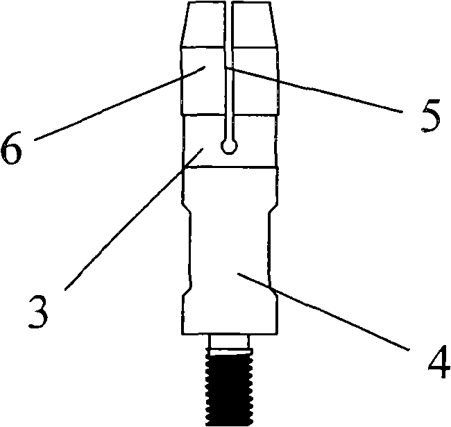
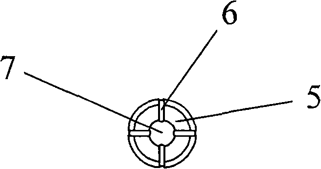
[0018] Such as Figure 1-Figure 3 As shown, this structure is suitable for inserts 4 with smaller volume and lighter weight, the outer diameter of the insert core 3 is slightly larger than the inner diameter of the insert core hole 2, at the end of the insert core 3 A groove body 6 is evenly opened, and an axial inner hole 7 is opened in the center, and the insert core 3 is divided into a certain number of elastic compression blocks 7; when the insert core 3 is inserted into the hole, due to the opening of the groove body 6 and the inner hole 7, the tail of the insert core 3 is retracted, and because the outer diameter of the insert core 3 is slightly larger than the inner diameter of the insert core hole 2, there is an interference, which can give the inserted insert The core 3 provides sufficient friction so that the insert core 3 will not fall off from the insert core hole 2 on the mold body 1 .

Embodiment 2

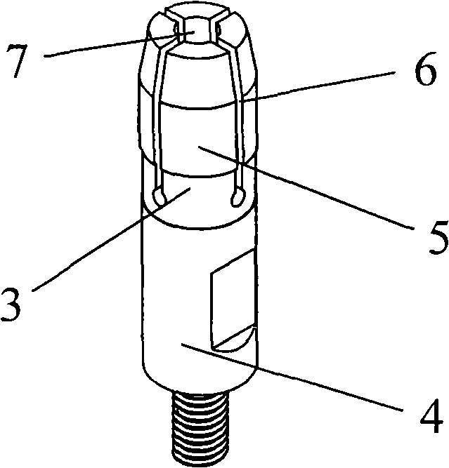
[0020] Such as Figure 4-Figure 6 As shown, this structure is suitable for inserts 4 with larger volume and heavier weight. It is a further improvement on the basis of Embodiment 1. It sets the axial inner hole 7 in the center of the insert core 3 It is square, and then two transversely crossed springs 8 are pressed into the square inner hole 7, and the four elastic pressing blocks 5 at the tail end of the insert core 3 are stretched by the elastic force of the spring 8, and the inserted insert The core 3 provides sufficient friction so that the insert core 3 will not fall off from the insert core hole 2 on the mold body 1 .


PUM


Abstract

The invention relates to an insert-fixing device of a compaction forming die, comprising an insert and a die body. An insert die core is arranged at the tail end of an insert, and the die body is provided with a corresponding insert die core hole and mutually connected and the inset. The insert-fixing device of the compaction forming die is characterized in that the outside diameter of the insertdie core is slightly larger than the inside diameter of the insert die core hole, the tail end of the insert die core is uniformly provided with grooves, the center of the insert die core is providedwith an axial inner hole, and the insert die core is divided into a certain amount of elastic compact blocks. In the invention, the insert die core is divided into a certain amount of elastic compactblocks which shrink at the tail of the insert die core when the insert die core is inserted into the insert die core hole because the outside diameter of the insert die core is slightly larger than the insert die core hole to have a shrink range; and accordingly, the insert can not fall off from the die body due to friction. In addition, a spring is additionally mounted in the inner hole so as tofurther improve the friction and be safer and more reliable to mount the insert.

Description

technical field [0001] The invention belongs to the technical field of mold manufacturing, in particular to a compression molding mold insert fixing device. Background technique [0002] Compression molding is to fix the mold on the hydraulic press, and close the upper and lower molds of the mold by the closing movement of the hydraulic press, and at the same time, heat and pressurize the material put into the mold cavity, so that the material is solidified and formed into a plastic product. Hydraulic presses generally move up and down. When there are inserts in plastic products and the inserts inevitably appear in the direction of the upper mold of the mold, it is difficult to install the inserts before the mold is closed. [0003] When the insert fixed on the insert core is loaded into the mold, it will be affected by gravity and may fall into the mold cavity, causing the mold to be crushed. In the prior art, in order to solve such problems, some magnets are placed on the...

Claims


Application Information

Patent Timeline
Patent Type & Authority Patents(China)
IPC IPC(8): B29C33/12
Inventor 尤华炜朱玲冯伟祖王为庆
Owner 无锡品源科技咨询有限公司
Why Eureka
Try Eureka