
A limit structure of button and electronic equipment

A limit structure and button technology, which is applied to electrical equipment shells/cabinets/drawers, circuits, electric switches, etc., can solve problems such as damage to electronic equipment, button installation failure, and button sinking, and achieve safe and reliable installation and use. Responsive, easy-to-install effects

Active Publication Date: 2021-06-01
OPPO CHONGQING INTELLIGENT TECH CO LTD
View PDF5 Cites 0 Cited by
  • Summary
  • Abstract
  • Description
  • Claims
  • Application Information

AI Technical Summary

Problems solved by technology

If the distance between the end of the elastic member and the sliding space is too long, it will be difficult for the end of the elastic member to slide in the sliding space. When installing the button, it will be difficult to fit the button into the housing due to the insensitive sliding of the end of the elastic member. , if the key is used, for example, when the key is pressed, because the end of the elastic member slides insensitively, it will be difficult to press and affect the feel of the key; if the distance between the end of the elastic member and the sliding space is too short, it will cause the elastic The end of the button is easy to get out of the sliding space. Once out of the sliding space, the button installation will fail or the button will sink, and the electronic equipment will be damaged and can no longer be used.
[0004] In order to make the end of the elastic member not easily out of the sliding space, an interference fit is used between the end of the elastic member and the sliding space in some related technologies, and the interference fit makes the end of the elastic member relatively tight in the sliding space. Difficult to slide and make the buttons more difficult to install or affect the feel when using

Method used


Image

  • A limit structure of button and electronic equipment
  • A limit structure of button and electronic equipment
  • A limit structure of button and electronic equipment

Examples


Embodiment Construction

[0026] The present invention will be described in further detail below in conjunction with the accompanying drawings and embodiments. In particular, the following examples are only used to illustrate the present invention, but not to limit the scope of the present invention. Likewise, the following embodiments are only some but not all of the embodiments of the present invention, and all other embodiments obtained by persons of ordinary skill in the art without creative efforts fall within the protection scope of the present invention.

[0027] Reference herein to an "embodiment" means that a particular feature, structure, or characteristic described in connection with the embodiment can be included in at least one embodiment of the present invention. The occurrences of this phrase in various places in the specification are not necessarily all referring to the same embodiment, nor are separate or alternative embodiments mutually exclusive of other embodiments. It is understoo...


PUM


Abstract

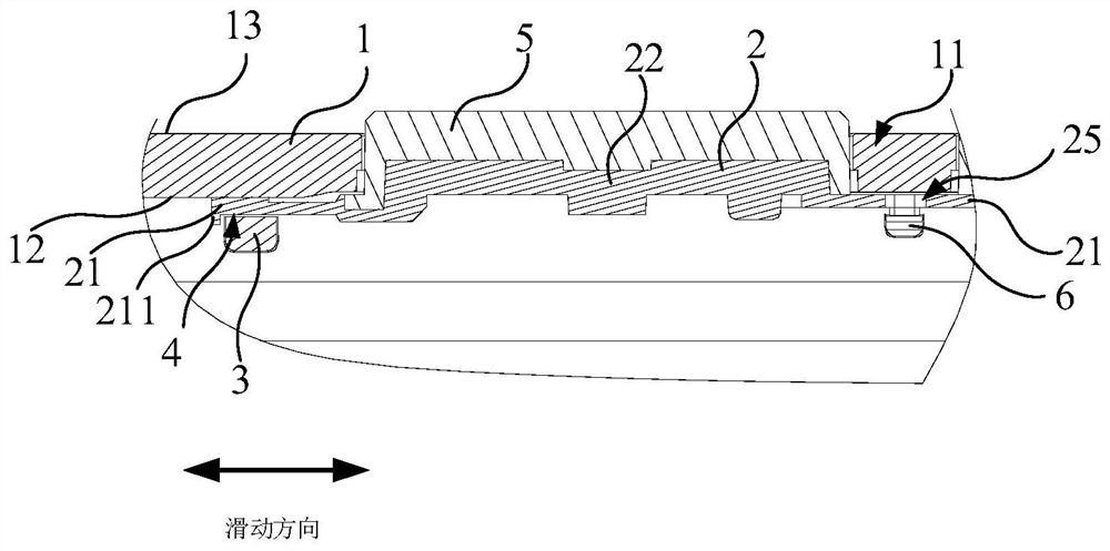
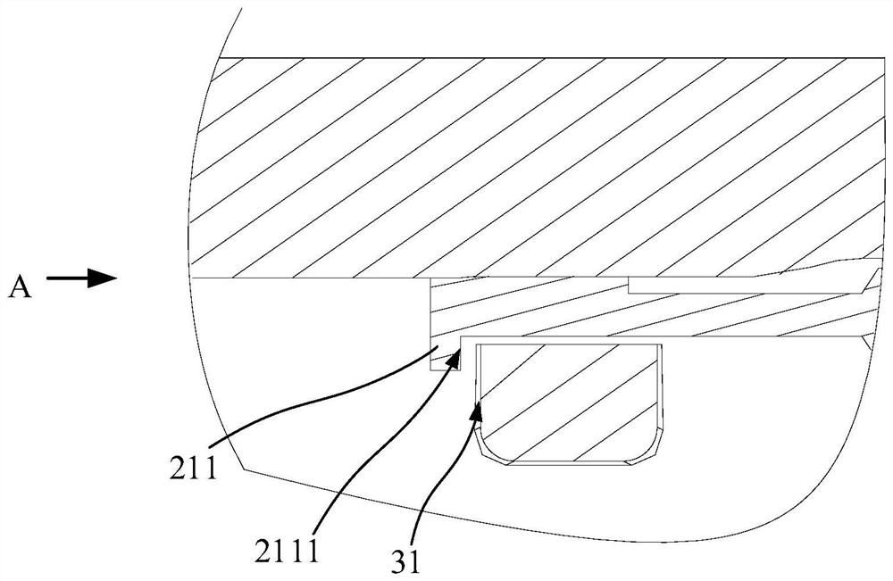
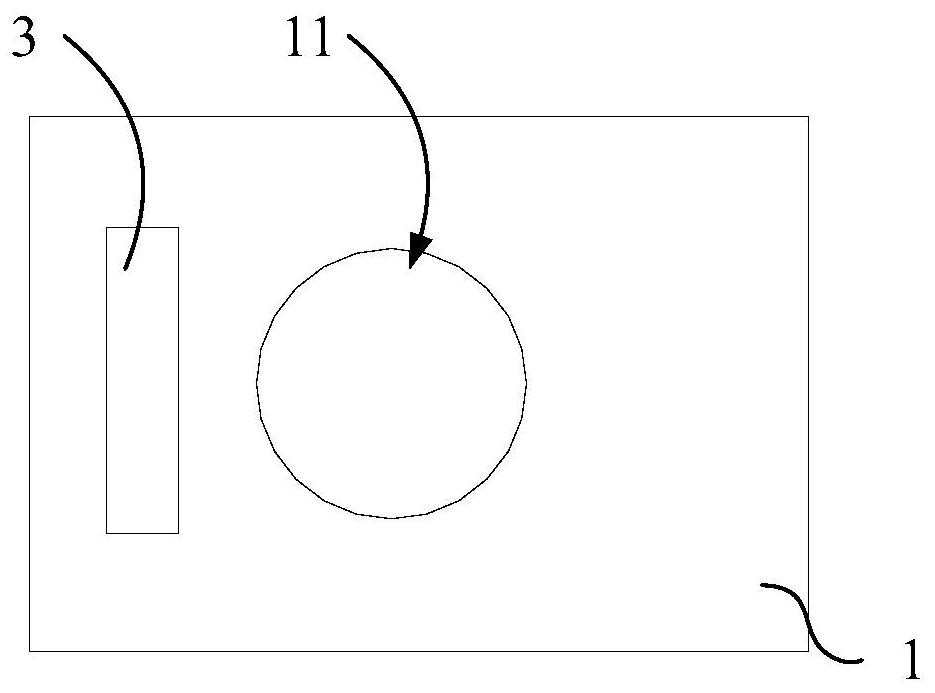
The present application provides a limiting structure of a button and an electronic device, the electronic device includes a housing and an elastic member; a button hole is provided on the housing, and the first side of the housing is adjacent to the button hole A fixed block is fixed at the position of the fixed block, and a sliding space is provided in the fixed block with a clearance fit with the end of the elastic member or the fixed block and the housing cooperate to form a sliding space; the end of the elastic member It can slide in the sliding space, and the end of the elastic member is provided with a limiting portion that prevents the end of the elastic member from breaking out of the sliding space. The limiting structure is more convenient to install and safer and more reliable to use.

Description

technical field [0001] The present invention relates to the technical field of electronic equipment, in particular to a position-limiting structure of a button and electronic equipment. Background technique [0002] In the related art, the button of the electronic device has a relatively large relationship with the structure of the elastic member during installation and use. [0003] When the button is installed or pressed, the button holds the elastic piece so that the elastic piece stretches, and the end of the elastic piece moves toward or away from the button, and the end of the elastic piece is clamped between the housing and the housing. In the sliding space formed by the fixed block, the end of the elastic member slides in the sliding space. If the distance between the end of the elastic member and the sliding space is too long, it will be difficult for the end of the elastic member to slide in the sliding space. When installing the button, it will be difficult to fi...

Claims


Application Information

Patent Timeline
Patent Type & Authority Patents(China)
IPC IPC(8): H01H13/02H01H13/14H01H13/26H05K5/02
CPCH01H13/02H01H13/14H01H13/26H05K5/0217H05K5/0247
Inventor 李瑞生
Owner OPPO CHONGQING INTELLIGENT TECH CO LTD
Learn More