Control method for internal combustion engine system, and internal combustion engine system

A control method and internal combustion engine technology, applied in the direction of engine control, internal combustion piston engine, combustion engine, etc., can solve the problems of inability to provide power, consumption, and inability to ensure power by universal batteries

Inactive Publication Date: 2009-09-30
MAZDA MOTOR CORP
View PDF5 Cites 18 Cited by
  • Summary
  • Abstract
  • Description
  • Claims
  • Application Information

AI Technical Summary

Problems solved by technology

In such a case, the electric power stored in the starting battery will be consumed when the internal combustion engine stops, causing the starting battery to fall into an overload state exceeding the design specification
If the starter battery is used in such an overloaded state, it may not be possible to secure sufficient power when the internal combustion engine is restarted.
[0004]...

Method used


Image

  • Control method for internal combustion engine system, and internal combustion engine system
  • Control method for internal combustion engine system, and internal combustion engine system
  • Control method for internal combustion engine system, and internal combustion engine system

Examples


no. 1 approach

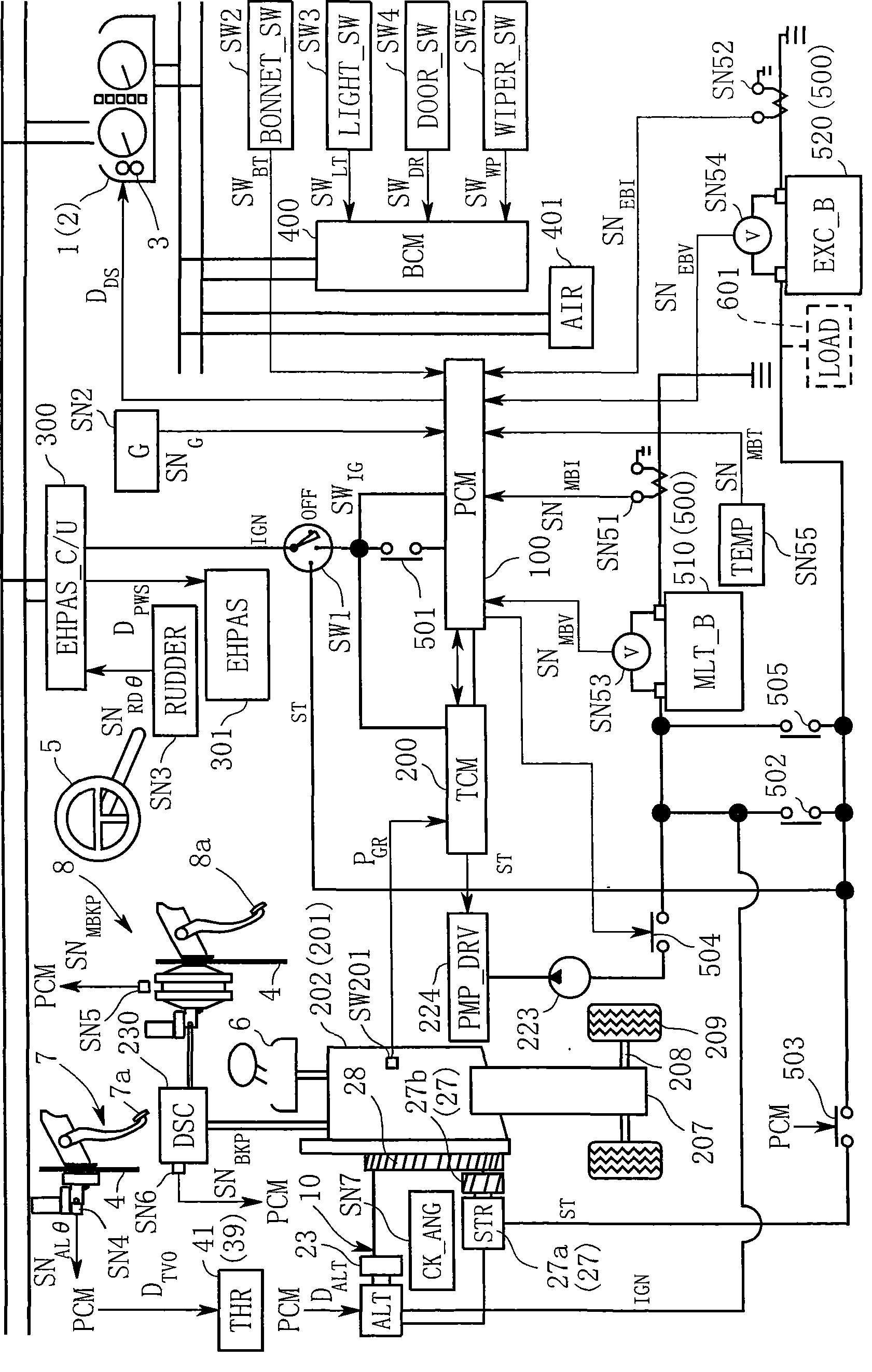
[0048] figure 1 It is a schematic configuration diagram of the internal combustion engine system according to the first embodiment of the present invention.

[0049] refer to figure 1 , the system includes: a power train control module (PCM: Powertrain Control Module) 100 that controls an engine 10 as an internal combustion engine; a transmission control module (TCM: Transmission Control Module) 200 that controls a transmission 201 equipped with the engine 10; and a control steering unit Steering Control Module (SCM: Steering Control Module) 300 at 301 ; Body Control Module (BCM: Body Control Module) 400 that controls various convenience switches SW2 to SW5 equipped in the vehicle body. In addition, each of the modules 100 to 400 is a logical structure, and actually a plurality of modules may be constructed in one system, or one module may be constructed in a plurality of systems. Among these modules 100 to 400, at least the powertrain control module 100 as a whole serves as...

no. 2 approach

[0150] Next, a second embodiment will be described.

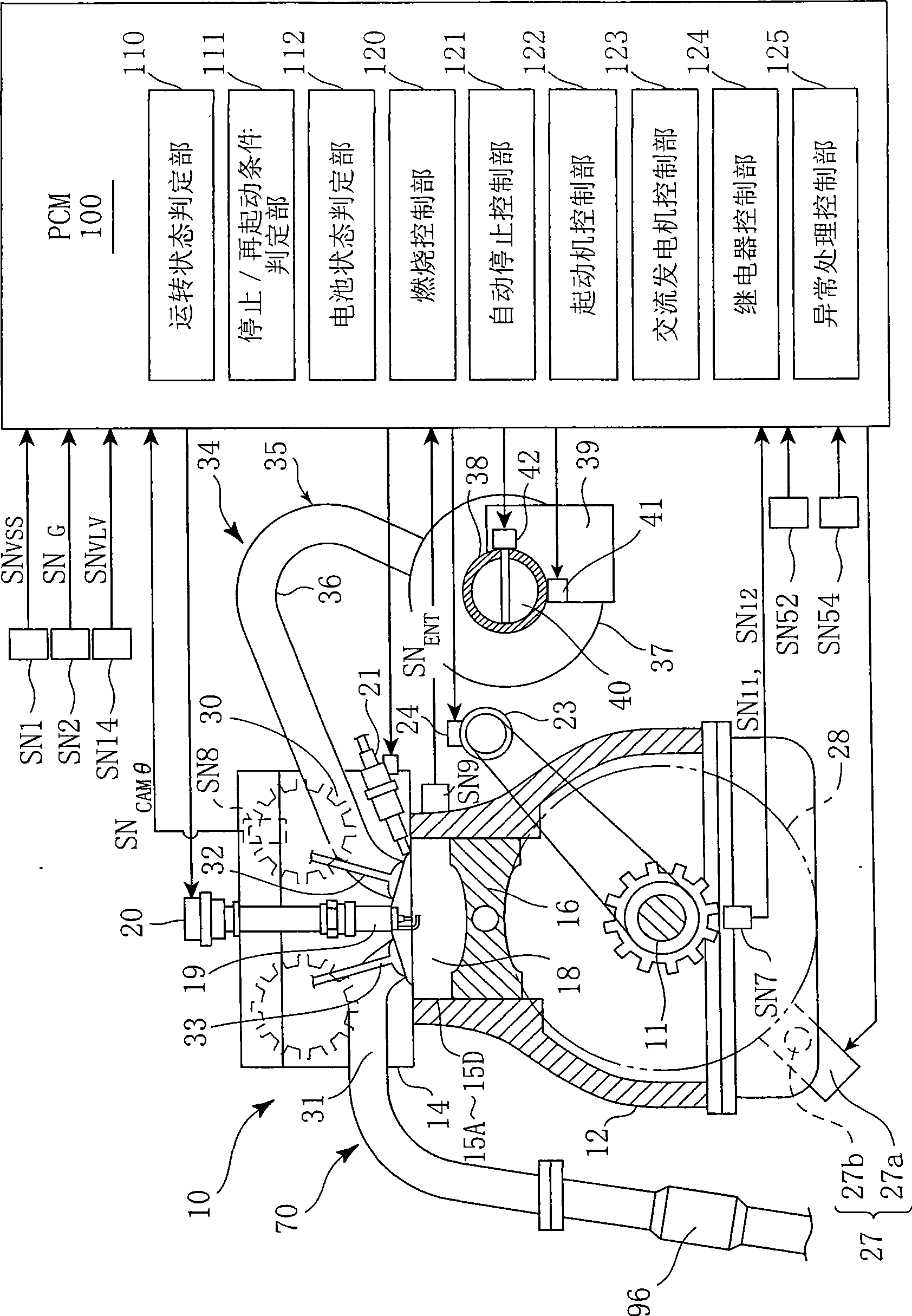
[0151] Figure 8 is a schematic configuration diagram of an internal combustion engine system according to a second embodiment of the present invention, Figure 9 It is a schematic configuration diagram mainly showing a cross section of an engine in an internal combustion engine system according to a second embodiment of the present invention.

[0152] Referring to the drawings, the power train of the second embodiment has a transmission embodied as a transmission 201, and a clutch pedal 311 of a clutch pedal unit 310 is equipped in a vehicle compartment.

[0153] Figure 10 It is a schematic configuration diagram showing a configuration of a manual transmission 201 mounted on a vehicle according to the present embodiment, and a configuration of a clutch pedal unit 310 for clutching and disengaging a clutch 204 included in the manual transmission 201 .

[0154] refer to Figure 8 and Figure 10, the manual transmission...


PUM


Abstract

The invention relates to a control method for an internal combustion engine system, capable of preventing an internal combustion engine in a state after being automatically stopped, from falling into an unrestartable state. Upon satisfaction of a given automatic stop condition, the engine 10 being running is automatically stopped (Step 11). A value of current I EBAT flowing out of a starter battery 520 is compared with a given current value I EBAT_TH , in an automatically stopped state of the engine 10 (Step S30) to diagnosis a discharging status of the starter battery 520. If a result of the diagnosis indicates that the value of current I EBAT flowing out of the starter battery 520 is greater than the given current value I EBAT_TH , it is determined that a post-attached load is detected, and the engine 10 is restarted irrespective of the satisfaction or non-satisfaction of a given restart condition. The situation of stopped internal combustion engine refusal to start can be prevented by using the invention.

Description

technical field [0001] The present invention relates to a control method of an internal combustion engine system and the internal combustion engine system, and in particular to a control method and the internal combustion engine system for automatically stopping the internal combustion engine when a predetermined automatic stop condition is satisfied, and then automatically restarting the internal combustion engine by using an electric drive device. Background technique [0002] For example, as disclosed in Japanese Patent Laid-Open Publication No. 2002-118978 (hereinafter referred to as "Patent Document 1"), this type of control device for a vehicle internal combustion engine automatically stops the internal combustion engine when a predetermined internal combustion engine stop condition is satisfied. After the internal combustion engine is automatically stopped, when the predetermined restart conditions are met, at least when the internal combustion engine is stopped, the e...

Claims


Application Information

Patent Timeline
IPC IPC(8): F02D29/02
CPCY02T10/48
Inventor 名越匡宏铁野雅之吉田胜正
Owner MAZDA MOTOR CORP
Why Eureka
Try Eureka