An engine oil circulation and drainage device of an air compressor

A technology of air compressor and drainage device, which is applied in the direction of machine/engine, mechanical equipment, liquid variable capacity machinery, etc., can solve the problems of small size, pollution, waste of the environment, etc.

Inactive Publication Date: 2009-09-30
ZHEJIANG HONGYOU AIR COMPRESSOR MFG
View PDF0 Cites 6 Cited by
  • Summary
  • Abstract
  • Description
  • Claims
  • Application Information

AI Technical Summary

Problems solved by technology

[0004] The above approach is obviously unreasonable. Firstly, it is a waste to drain the oil in the gas tank without recycling it, which will pollute the environment. Secondly, the traditional oil-gas separation device is too small to separate the oil and gas. The position of the purge valve is too low, which is not conducive to operation and observation

Method used


Image

  • An engine oil circulation and drainage device of an air compressor
  • An engine oil circulation and drainage device of an air compressor
  • An engine oil circulation and drainage device of an air compressor

Examples


Embodiment Construction

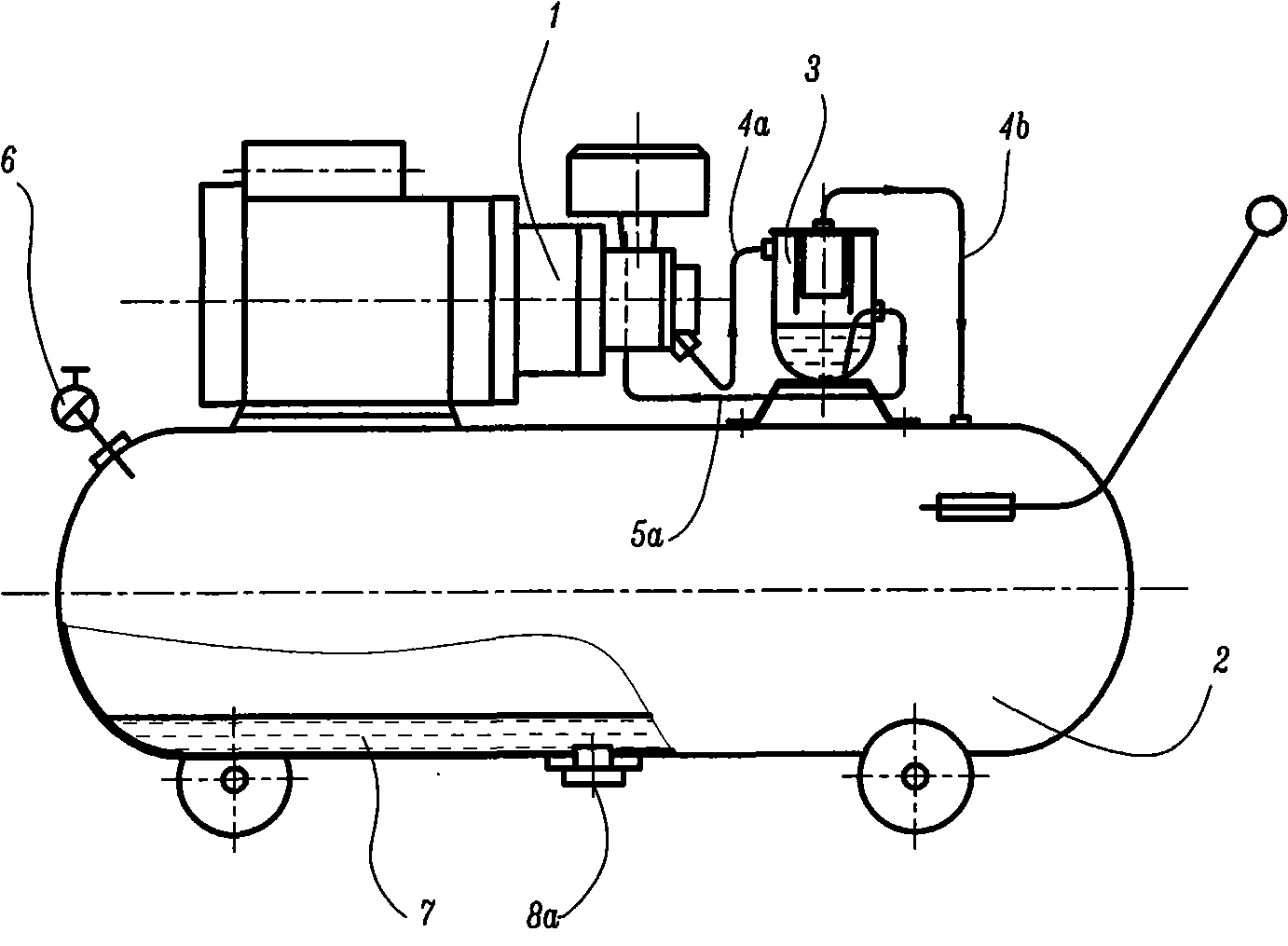
[0014] figure 1 Shown is a schematic diagram of the traditional air compressor oil circulation and drainage device layout, including air compressor 1, air tank 2, oil-gas separator 3, exhaust pipe 4a, connecting pipe 4b, oil return pipe 5a, air supply valve 6 and cleaning Dirty valve 8a, in which the high-temperature and high-pressure air discharged from the air compressor 1 is connected to the oil-air separator 3 through the exhaust pipe 4a, most of the oil is separated and falls into the bottom oil pool of the oil-air separator 3, and circulates through the oil return pipe 5a Return to the air compressor 1, and the separated air enters the air tank 2 through the connecting pipe 4b. Under the deceleration and cooling of the air tank 2, the moisture in the high-pressure air and a small amount of remaining engine oil are condensed and accumulated in the air tank The bottom of the gas tank 2 forms a fouling 7, and the fouling 7 is finally discharged through the purge valve 8a ar...


PUM


Abstract

The invention relates to an engine oil circulation and drainage device of an air compressor, comprises an air compressor 1, a vent pipe 4a and a gas tank 2 and is characterized in that air vented by the air compressor 1 is directly guided into the gas tank 2 through the vent pipe 4a, which means the gas tank 2 serves as an oil and gas separator; a built-in oil and gas separator 9 is arranged between the gas tank 2 and an air supply valve 6 in order to get cleaner air supply and an air-off automatic oil return valve is distributed on the built-in oil and gas separator 9; besides, an oil water trap 10 is arranged and oil and water separated from the gas tank 2 are guided out through an oil guide pipe 5b and go into the oil water trap 10 and return to the air compressor 1 through an oil suction pipe 10d, a control valve 12 and an oil return pipe 5a. Finally, a drain valve 8b and a visualized oil water observer 11 are also arranged on the oil water trap 10 for the convenience of drainage operation and observation of the storage status of oil and gas.

Description

technical field [0001] The invention relates to a machine oil circulation and drainage device, in particular to an air compressor machine oil circulation and drainage device. Background technique [0002] At present, many air compressors are oil-lubricated compressors, and a considerable part of them need to use a large amount of oil during operation, such as vane machines, scroll machines, and screw machines. In these oil-lubricated air compressors, a lot of oil is discharged together with the high-pressure air. In order to reduce the consumption of oil, the traditional method is to use an oil-gas separator to separate the oil from it for recycling, and the separated oil Cleaner high-pressure air is stored in tanks. [0003] The problem is that under the influence of high temperature, lubricating oil is often mixed with high-pressure air in the form of mist and discharged from the exhaust port of the compressor at high speed. It is difficult for ordinary oil-gas separators...

Claims


Application Information

Patent Timeline
Patent Type & Authority Applications(China)
IPC IPC(8): F04B39/02
Inventor 陈君立阮勤江耿爱农李辛沫倪桂樵
Owner ZHEJIANG HONGYOU AIR COMPRESSOR MFG
Why Eureka
Try Eureka