Special metal pipe for heat pipes, and manufacturing method thereof
A manufacturing method and technology of metal pipes, applied in the field of metal pipes, can solve problems such as difficulty in coating shunt partitions and increased difficulty in making heat pipes, etc.
- Summary
- Abstract
- Description
- Claims
- Application Information
AI Technical Summary
Problems solved by technology
Method used
Image
Examples
no. 1 example
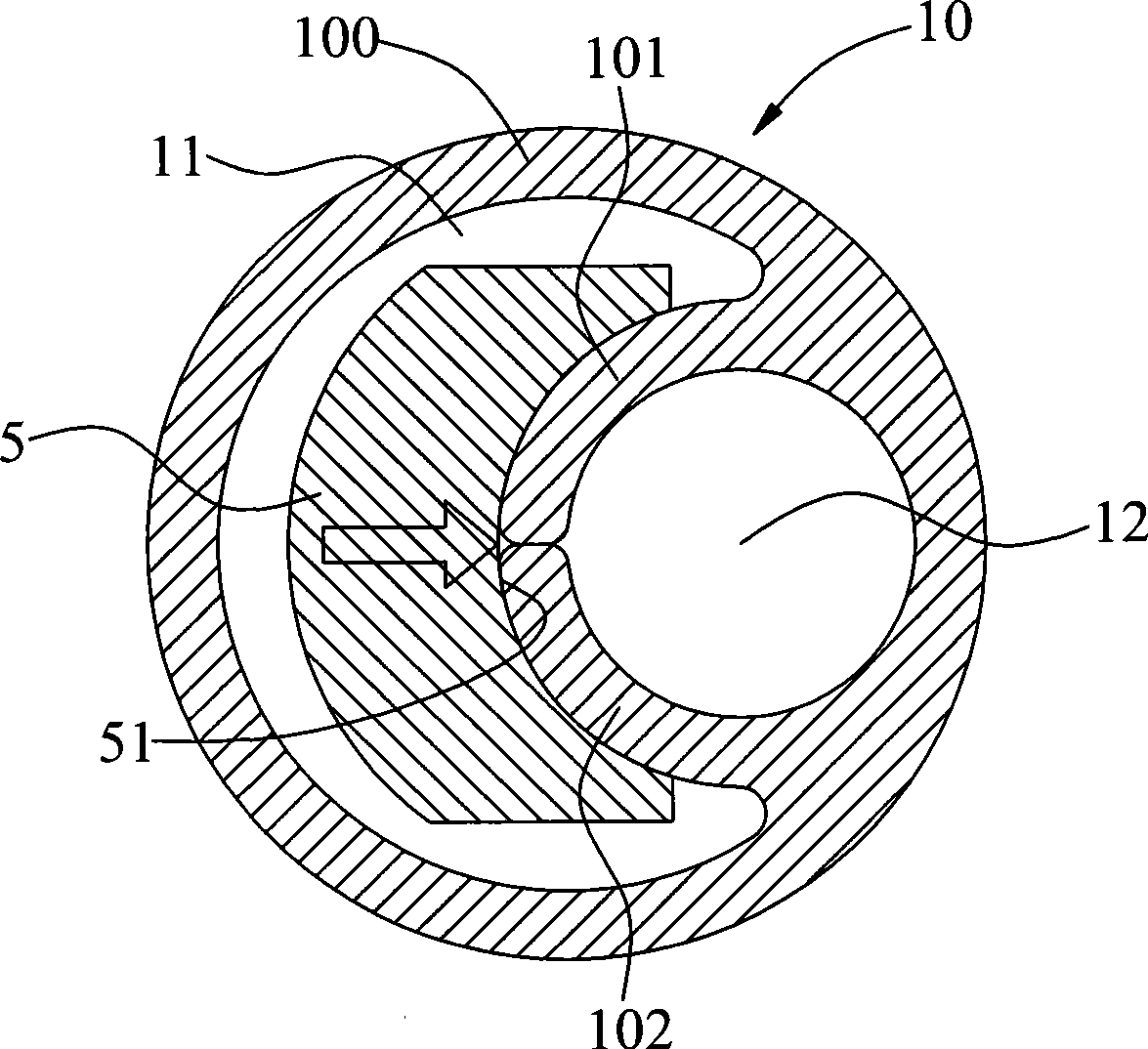
[0040] The invention provides a special metal pipe for heat pipe, such as image 3 As shown, the metal tube 10 mainly includes a tube body (Tube) 100, two partition plates 101, 102 extend from the inner wall of the tube body 100, and a gas channel 11 (Vapor Channel) is formed to partition the inside of the tube body 100 And the liquid channel 12 (Liquid Channel); the length of the liquid channel 12 of the present embodiment is less than the length of the gas channel 11, so that the first and last ends of the gas channel 11 are respectively formed with a communication zone 13 (such as Figure 4 shown).
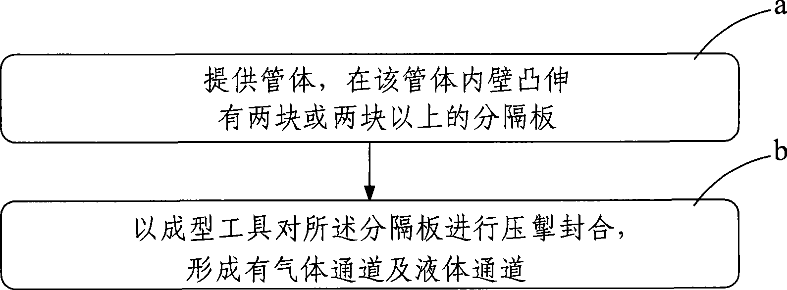
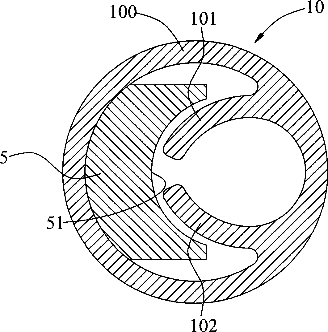
[0041] Please refer to Figure 1 to Figure 4 As shown, they are respectively the flow chart of the first manufacturing method of the metal pipe of the present invention; the radial cross-sectional schematic diagram before being processed by the forming tool in the first embodiment of the pipe body of the metal pipe of the present invention; the metal pipe of the present invent...
no. 2 example
[0048] Please refer to Figure 7 to Figure 9 Shown is the flow chart of the second manufacturing method of the metal pipe of the present invention; the radial cross-sectional schematic diagram of the second embodiment of the pipe body of the metal pipe of the present invention; Figure 8 Schematic diagram of the radial cross-section of the middle tube body after being processed by the press tool. The production method of this embodiment replaces the step b) of the above-mentioned first embodiment with step b'). The inside of 100 is separated and formed with gas channel 11 and liquid channel 12 (such as Figure 8 , Figure 9 shown); in this step, the upper and lower clamping pressure tools (not shown) are pressed against the outer surface of the pipe body 100, so that the end faces of the two upright partition plates 101, 102 are mutually It is bonded and sealed, and a gas channel 11 and a liquid channel 12 are formed inside the tube body 100 .
[0049] In addition, by step...
no. 3 example
[0051] Please refer to Figure 10 and Figure 11 Shown, respectively is the radial section schematic diagram of the third embodiment of the pipe body of the metal pipe of the present invention and Figure 10 The schematic diagram of the radial cross section of the middle pipe body after being processed by the press tool. The difference between it and the second embodiment is that this embodiment is in the form of a single upright partition plate 101, and the outer surface of the pipe body 100 is processed by a press tool. Press and hold, so that the end surface of the partition plate 101 and the inner wall of the tube body 100 are bonded and sealed together, and a gas channel 11 and a liquid channel 12 are formed inside the tube body 100; and the gas channel 11 and the liquid channel 12 are in the tube body The first and last ends of 100 are connected to each other (not shown in the figure); thus, it also has the equivalent effect of the above-mentioned embodiment.
PUM
 Abstract
Description
Claims
Application Information
 - R&D
- Intellectual Property
- Life Sciences
- Materials
- Tech Scout
- Unparalleled Data Quality
- Higher Quality Content
- 60% Fewer Hallucinations
Browse by: Latest US Patents, China's latest patents, Technical Efficacy Thesaurus, Application Domain, Technology Topic, Popular Technical Reports.
© 2025 PatSnap. All rights reserved.Legal|Privacy policy|Modern Slavery Act Transparency Statement|Sitemap|About US| Contact US: help@patsnap.com


