Check patentability & draft patents in minutes with Patsnap Eureka AI!

Ultra-thin large-screen micro-display rear projection display device

A technology for a display device and a large screen, which is applied in the direction of using a projection device image reproducer, a projection device, a TV, etc., and can solve the problem that the distance between the reflection point of the optical axis of the large mirror and the screen is large, which affects the popularization and application of the micro-display rear projection display, Occupying the space area of ​​the user and other issues, to achieve the effect of reducing human damage, increasing the price, and shortening the optical path

Inactive Publication Date: 2009-09-30
郑占青 +1
View PDF0 Cites 2 Cited by
  • Summary
  • Abstract
  • Description
  • Claims
  • Application Information

AI Technical Summary

Problems solved by technology

Yet existing micro-display rear-projection display is because the large and small reflectors are plane reflectors, in order to correct the trapezoidal deformation that figure reflection causes, so there are limitations on the oblique setting angle of the large and small reflectors (that is, the large and small two reflectors and the The intersection angle of the screen surface is between 34 degrees and 37 degrees), so that the distance between the reflection point of the optical axis of the large mirror and the screen is too large, and finally the thickness of the whole machine is too thick, which affects the appearance and takes up more space for the user area, which has seriously affected the popularization and application of micro-display rear-projection displays in the office field, video conferencing, school multimedia classrooms, and home theaters.

Method used


Image

  • Ultra-thin large-screen micro-display rear projection display device
  • Ultra-thin large-screen micro-display rear projection display device

Examples


Embodiment Construction

[0019] The embodiments of the present invention will be described in further detail below in conjunction with the accompanying drawings, but the present embodiments are not intended to limit the present invention, and any similar structures and similar changes of the present invention should be included in the protection scope of the present invention.

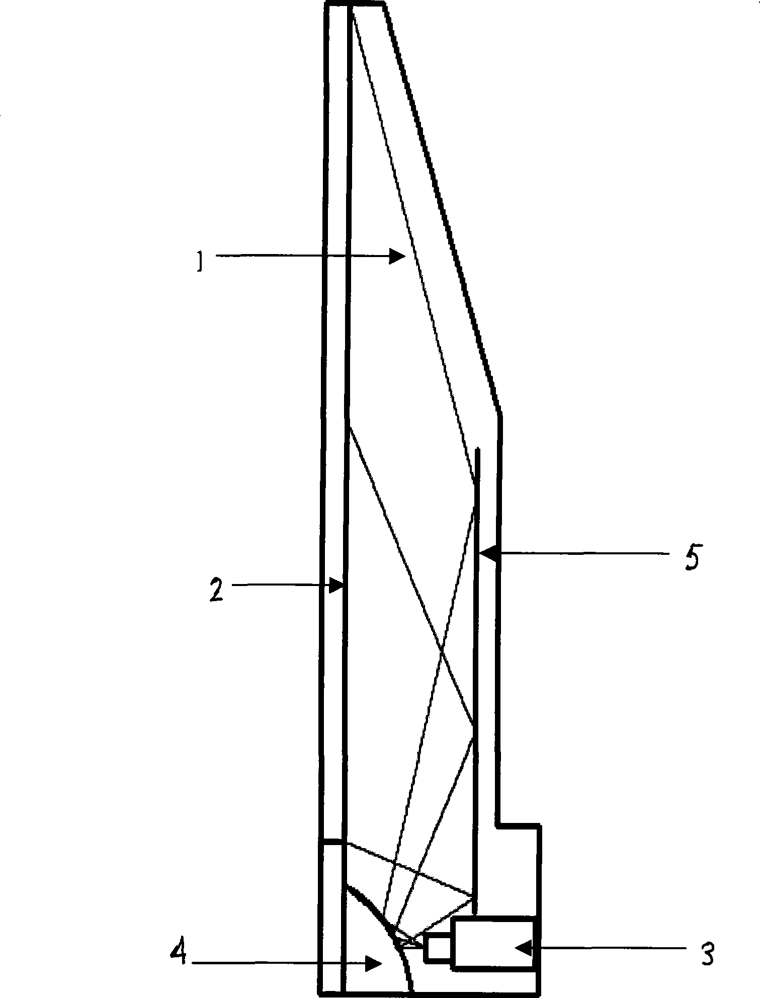
[0020] Since the invention of this technology changes the angle of the placement position of the large reflector, if the previous method of flat small reflector is still used, the distance from the light coming out of the optical engine lens at the same angle in the opposite direction to the screen will be different. , so the image will form a trapezoid. When the optical axis is perpendicular to the reflection of the imaging plane, define Y as the projection size, X as the projection distance, B as the angle between the projection light and the optical axis, m as the relationship coefficient between X and B, and k as a constant...


PUM


Abstract

The invention discloses an ultra-thin large-screen micro-display rear projection display device, which relates to the technical field of rear projection display, and aims to solve the technical problem of projection distance of large-screen micro-display rear projection display devices. The micro-display rear projection display device comprises a machine shell, a screen arranged at the front face of the machine shell, as well as an optical engine, a small reflecting mirror and a large reflecting mirror which are arranged in the machine shell, wherein an optical signal emitted by the optical engine is orderly subjected to the reflection of the small reflecting mirror and the large reflecting mirror and finally projects onto the screen; the small reflecting mirror is a small reflecting mirror with an arc surface and is placed under the screen; and the large reflecting mirror is arranged behind the screen and is parallel to the screen. The device has the remarkable characteristic of shortening the projection distance due to adopting the reflection of the small reflecting mirror with the arc surface so as to ensure that the large-screen micro-display rear projection display device is suitable for office fields, video conferences, school multi-media classrooms and home theaters.

Description

technical field [0001] The invention relates to rear projection display technology, in particular to an ultra-thin large-screen micro-display rear projection display device used in office fields, video conferencing, school multimedia classrooms, and home theaters. Background technique [0002] Traditional micro-rear-projection displays, including projection-type micro-rear-projection displays and reflective-type micro-rear-projection displays, that is, LCD rear-projection displays and LCOS, DLP (Digital Micromirror Device, translated as digital light processor) rear-projection displays, generally Including illumination optical system, color light separation optical system, electro-optic device, color light synthesis system, projection optical system and screen. In the micro-display rear-projection display, the separated three-color light (red, green, blue) passes through the electro-optic device and the color-light synthesis system, and finally projects onto the screen throu...

Claims


Application Information

Patent Timeline
Patent Type & Authority Applications(China)
IPC IPC(8): G03B21/28G02B5/08H04N5/74H04N9/31
Inventor 李卫华郑占青
Owner 郑占青
Features
  • R&D
  • Intellectual Property
  • Life Sciences
  • Materials
  • Tech Scout
  • Unparalleled Data Quality
  • Higher Quality Content
  • 60% Fewer Hallucinations
Learn More