Supercharge Your Innovation With Domain-Expert AI Agents!

Image displaying apparatus and image displaying method

A technology for image display devices and display units, which is applied to static indicators, instruments, etc., can solve problems such as degradation and generation of thin strips of image quality, and achieve the effect of avoiding deterioration of image quality and preventing thin stripes in the horizontal direction

Inactive Publication Date: 2009-09-30
SONY CORP
View PDF7 Cites 18 Cited by
  • Summary
  • Abstract
  • Description
  • Claims
  • Application Information

AI Technical Summary

Problems solved by technology

[0053] However, when the deviation correction process of the threshold voltage Vth is performed simultaneously on a plurality of lines in this way, there is a subtle difference in light emission luminance between these lines, and as a result, thin stripes are generated in the horizontal direction, and it is judged that the image quality is deteriorated.

Method used


Image

  • Image displaying apparatus and image displaying method
  • Image displaying apparatus and image displaying method
  • Image displaying apparatus and image displaying method

Examples


Embodiment 1

[0093] (1) Structure of Embodiment 1

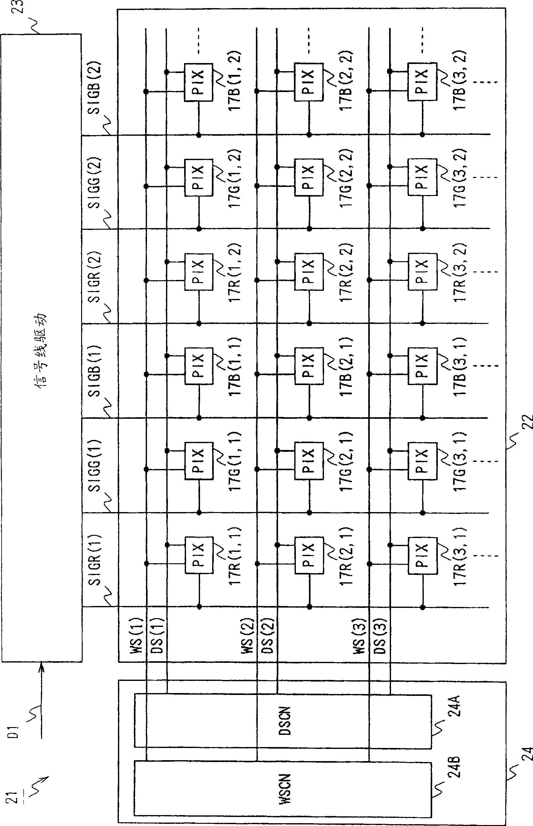
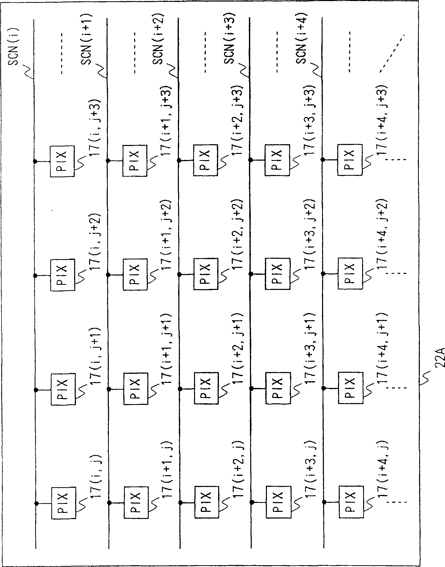
[0094] figure 2 is a block diagram showing a display device according to Embodiment 1 of the present invention. In the display device 21 , a display unit 22 is formed on a predetermined insulating substrate, and a signal line driving circuit 23 and a scanning line driving circuit 24 are provided around the display unit 22 . Here, the display unit 22 is formed by arranging red, green, and blue pixel circuits (PIX) 17R, 17G, and 17B in a matrix to form red, green, and blue pixels, respectively. In addition, these red, green, and blue pixel circuits 17R, 17G, and 17B are identical to Figure 18 The pixel circuit 17 is configured in the same manner. In addition, through the figure 2 contrast, such as image 3 As shown, the display unit 22A can also be widely applied by arranging monochrome pixel circuits 17 sequentially in a matrix instead of the red, green, and blue pixel circuits 17R, 17G, and 17B.

[0095] In this example, by using...

Embodiment 2

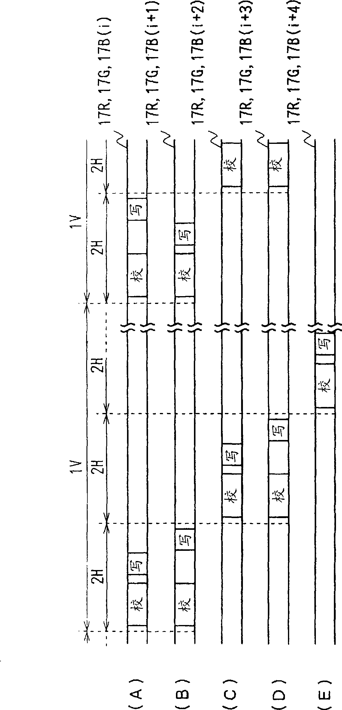
[0116] Figure 5 is used to pass the Figure 4 A timing chart of the operation of the display device according to Embodiment 2 of the present invention will be described by comparing with the above. The display device of this embodiment is similar to the display device of Embodiment 1 except that the timing of lowering the drive signal DS is set in the same way in two consecutive lines in which the deviation correction process of the threshold voltage of the driving transistor is simultaneously performed. We constitute in the same way.

[0117] That is, from the viewpoint of equalizing the light emission luminance between the lines, as shown in the display device 21 of the first embodiment, although it is desirable to make the light emission period between the lines equal, but when it is practically sufficient, as in this embodiment In these two consecutive lines, the timing of lowering the drive signal can be set identically, thereby simplifying the structure.

[0118] In ...

Embodiment 3

[0120] Image 6 is used to pass the figure 1 A timing chart of the operation of the display device according to Embodiment 3 of the present invention will be described by comparison with the present invention. The display device of this embodiment simultaneously executes the deviation correction process of the threshold voltages of the driving transistors in three consecutive lines. In addition, by sequentially switching the order of the gradation setting cyclically in the three consecutive lines, the order of the gradation setting is changed in the direction of the time axis among these three lines. In addition, through the Image 6 contrast, such as Figure 7 As shown, instead of switching the order of gradation setting cyclically sequentially in three consecutive lines, the order of gradation setting may be changed along the time axis direction by reversing the order in odd fields and even fields.

[0121] This embodiment is configured in the same manner as in the firs...


PUM


Abstract

In the inventive image displaying apparatus and image displaying method, such as display apparatus applied in active matrix type based on organic el element, when multi-lines simultaneous implement offset correction process of threshold voltage driving the transistor, the generation of horizontal direction fine strip is prevented to avoid the deterioration of image quality. When the multi-lines simultaneous implement offset correction process of threshold voltage driving the transistor in the invention, the sequence of the grey scale setting process relative to the threshold voltage offset correction process is changed along the time axis direction or the scan line direction.

Description

technical field [0001] The present invention relates to an image display device and an image display method, and can be applied to, for example, an active matrix display device based on an organic EL (Electro Luminescence) element. The present invention changes the order of the gray scale setting process with respect to the deviation correction process of the threshold voltage along the time axis direction and / or the scanning line direction in a plurality of lines simultaneously performing the deviation correction process of the threshold voltage of the driving transistor, thereby When the deviation correction processing of the threshold voltages of the driving transistors is performed simultaneously in a plurality of lines, it is possible to prevent occurrence of horizontal cords and effectively avoid deterioration of image quality. Background technique [0002] Conventionally, in an active matrix type display device using an organic EL element, a display unit is formed by ...

Claims


Application Information

Patent Timeline
Patent Type & Authority Applications(China)
IPC IPC(8): G09G3/32G09G3/20
CPCG09G2320/0247G09G2310/0262G09G2310/0251G09G2300/043G09G2320/0233G09G3/3233G09G2310/0208G09G3/20G09G3/30
Inventor 浅野慎山本哲郎内野胜秀
Owner SONY CORP
Features
  • R&D
  • Intellectual Property
  • Life Sciences
  • Materials
  • Tech Scout
  • Unparalleled Data Quality
  • Higher Quality Content
  • 60% Fewer Hallucinations
Learn More