Single base fluorescent lamp and illumination device

A technology for lighting fixtures and fluorescent lamps, which is applied in lighting installations, lighting and heating equipment, discharge lamps, etc. to achieve the effect of large luminous flux output

Active Publication Date: 2012-05-23
PANASONIC CORP
View PDF2 Cites 0 Cited by
  • Summary
  • Abstract
  • Description
  • Claims
  • Application Information

AI Technical Summary

Problems solved by technology

[0016]Once the ambient temperature is 25°C higher than the set temperature, the luminous flux output will drop, and the rated luminous flux may not be obtained

Method used


Image

  • Single base fluorescent lamp and illumination device
  • Single base fluorescent lamp and illumination device
  • Single base fluorescent lamp and illumination device

Examples


Embodiment Construction

[0063] Embodiment 1

[0064] Embodiments are described below with reference to the drawings.

[0065] 1. Structure of bulb-type fluorescent lamp

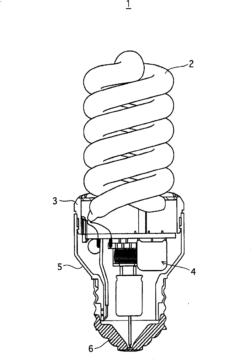
[0066] figure 1 It is a front view showing the bulb-type fluorescent lamp 1 .

[0067] Such as figure 1As shown, a single-base bulb-type fluorescent lamp 1 includes an arc tube 1 , a resin support member 3 , an electronic ballast 4 , a resin case 5 , and a base 6 .

[0068] The arc tube 2 has a helical portion bent into a double helical shape.

[0069] The resin support member 3 erects the luminous tube 2 by supporting both ends of the luminous tube 2 .

[0070] The bulb-type fluorescent lamp 1 has a structure in which the light-emitting tube 2 is not covered by a covering member and can directly contact the outside air (a structure without an envelope).

[0071] The resin case 5 accommodates the electronic ballast 4, and a lamp cap 6 is installed at the end.

[0072] 2. The structure of the luminous tube

[0073] figure...


PUM


Abstract

The present invention provides a single base fluorescent lamp of a compact self-ballasted type or the like which is capable of providing a peak light beam output when the lame is used in an illumination device. A lamp (1) comprises a light emitting tube (2) having a spiral part bent spirally, a pair of electrodes and a single curved discharge path therein; a holding resin member (3) for vertically installing the light emitting tube (2); and a base (6) for connecting the lamp to an illumination device. The fluorescent lamp can provide the maximum light beam output when the temperature around the lamp reaches a predetermined level equal to or higher than 30 DEG C.

Description

technical field [0001] The present invention relates to a single base type fluorescent lamp. Background technique [0002] Ushering in the era of energy saving, the development and research of various bulb-type fluorescent lamps as energy-saving light sources to replace incandescent lamps are progressing. [0003] Figure 15 It is a front view of a conventional light bulb type fluorescent lamp 101 as an example. [0004] The bulb-type fluorescent lamp 101 includes a double spiral arc tube 102 , an electronic ballast 103 , a container 104 supporting the arc tube 102 and housing the electronic ballast, and a base 105 . [0005] An example of the dimensions and specifications of the lamp 101 (hereinafter, the lamp will be referred to as "existing product") is as follows. [0006] Maximum diameterDo......45mm [0007] The total length of the lamp Lo.......104mm [0008] Tube inner diameter of the main part (the main part other than the front end of the arc tube 102) ... 7....

Claims


Application Information

Patent Timeline
Patent Type & Authority Patents(China)
IPC IPC(8): H01J61/30H01J61/16F21S2/00H01J61/72
CPCH01J61/16H01J61/20H01J61/327H01J61/33
Inventor 高桥晓良伊藤和彦高桥昭悟
Owner PANASONIC CORP
Why Eureka
Try Eureka