

Light source system and related projection system
A technology of a light source system and a laser light source, applied in optics, optical elements for changing the spectral characteristics of emitted light, lighting devices, etc., can solve the problems of increasing the cost of the light source system and the inability to effectively control the volume and cost of the light source system at the same time. To achieve the effect of cost control
- Summary
- Abstract
- Description
- Claims
- Application Information
AI Technical Summary
Problems solved by technology
Method used
Image

Examples
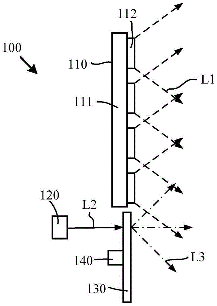
Embodiment 1
[0031] see figure 1 , figure 1 It is a side view of an embodiment of the light source system in the embodiment of the present invention. Such as figure 1 As shown, the light source system 100 includes a light emitting device including an LED array 110 , a laser light source 120 , a wavelength converting device 130 and a driving device 140 .
[0032] The LED array 110 includes a substrate 111 and a plurality of LED chips 112 disposed on the substrate 111 . The substrate 111 is preferably a copper substrate, and the LED chip can be fixed on the substrate 111 by welding, bonding or other connection methods. The LED chip array can be arranged in a matrix, in a line or in a concentric circle, etc., and can be designed according to different needs of the application field. The LED chip 112 is used to generate the first light L1.
[0033] The laser light source 120 can be a single laser diode, or a laser array composed of more than two laser diodes. The laser light source 120 i...
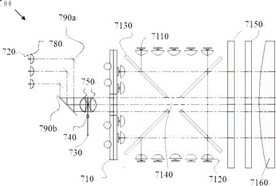
Embodiment 2
[0047] see Figure 2a and Figure 2b , Figure 2a It is a side view of another embodiment of the light source system in the embodiment of the present invention; Figure 2b yes Figure 2a Front view of the wavelength conversion device in the illustrated embodiment. As shown in FIG. 2 , the light emitting device of the light source system 200 includes an LED array 210 , a laser light source 220 , a wavelength converting device 230 and a driving device 240 . The LED array 210 includes a substrate 211 and a plurality of LED chips 212 .
[0048] This embodiment and figure 1 Differences in the illustrated embodiments include:
[0049] (1) The LED array 210 also includes a light-through hole 214, and the wavelength conversion device 230 is arranged on the back side of the light-emitting surface of the LED array 210, and the outgoing light L3 of the wavelength conversion device is incident on the back side of the light-emitting surface of the LED array and passes through. The l...
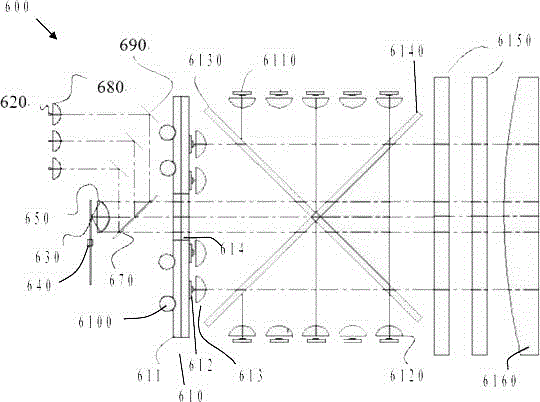
Embodiment 3
[0053] see image 3 , image 3 It is a side view of another embodiment of the light source system in the embodiment of the present invention. Such as image 3 As shown, the light emitting device of the light source system 300 includes an LED array 310 , a laser light source 320 , a wavelength converting device 330 , a driving device 340 and a collimating lens 350 . The LED array 310 includes a substrate 311 , a plurality of LED chips 312 and a collimating lens 313 .
[0054] This embodiment and Figure 2a Differences in the illustrated embodiments include:
[0055] The LED array of the light source system 300 does not include a light hole, but the light emitting device of the light source system 300 also includes a reflector 360, which is located on one side of the light emitting surface of the LED array, and the outgoing light L3 of the wavelength conversion device 330 is incident on the The reflecting device is reflected by the reflecting device to combine with the firs...
PUM
 Abstract
Description
Claims
Application Information