Frame structure for multi-hop relay in wireless communication systems

A wireless relay, frame structure technology, applied in wireless communication, radio transmission system, radio relay system and other directions, can solve the problems of increasing the error rate of wireless communication, weak signal strength, etc.

Inactive Publication Date: 2009-09-30
ZTE (USA) INC
View PDF2 Cites 5 Cited by
  • Summary
  • Abstract
  • Description
  • Claims
  • Application Information

AI Technical Summary

Problems solved by technology

At the edge of a radio cell, the signal strength can be weak and thus potentially increase the error rate in wireless communication

Method used


Image

  • Frame structure for multi-hop relay in wireless communication systems
  • Frame structure for multi-hop relay in wireless communication systems
  • Frame structure for multi-hop relay in wireless communication systems

Examples


Embodiment Construction

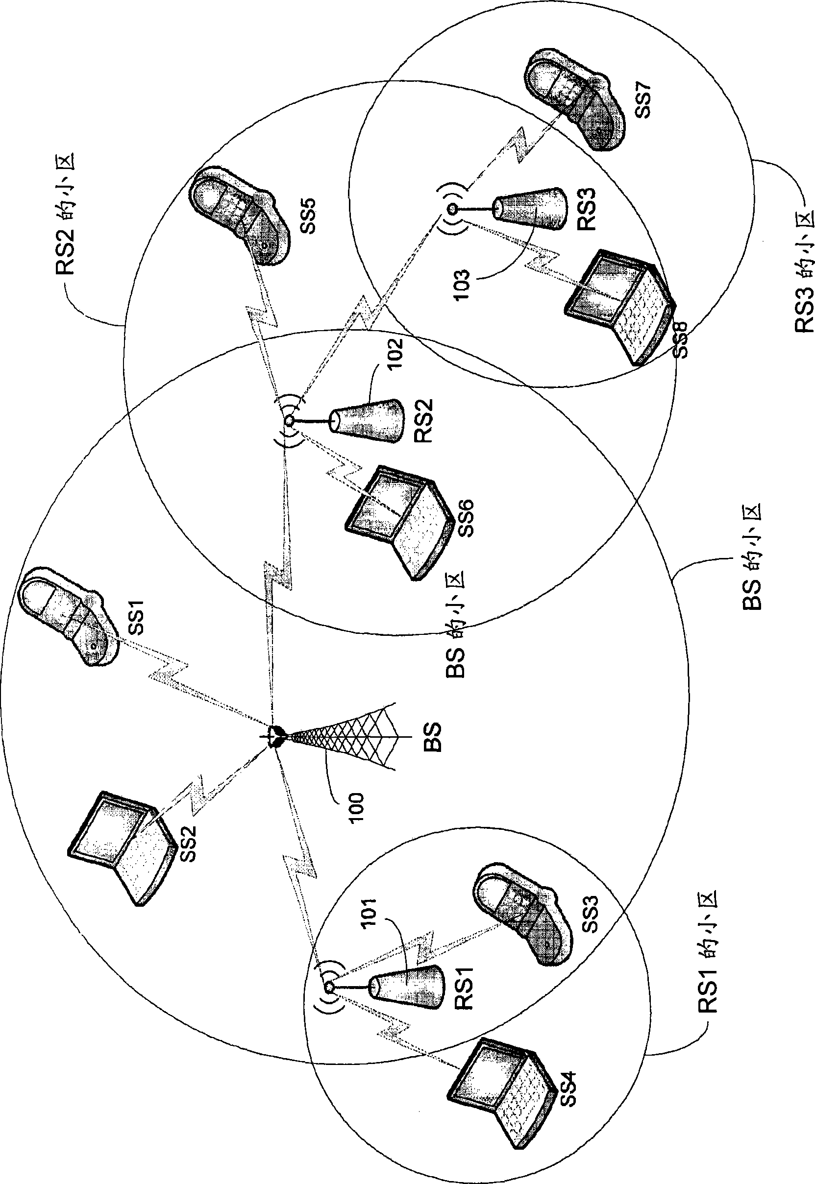
[0016] The Mobile Multi-Hop Relay (MMR) mode defined in IEEE 802.16j needs to be backward compatible with the published IEEE 802.16-2004 and IEEE 802.16e-2005 standards. It is expected to work with relay stations (RS) and MMR base stations (MMR-BS) without any changes to existing mobile stations (MS). Various types of relay stations (eg, fixed RS, nomadic RS, and mobile RS) and MMR-BSs will be defined in the IEEE 802.16j project task group (TGj). According to the IEEE 802.16j Project Approval Request (PAR), this modification is to improve coverage, throughput, and system capacity by specifying 802.16 multi-hop relay capabilities and functions of interoperable relay stations and base stations.

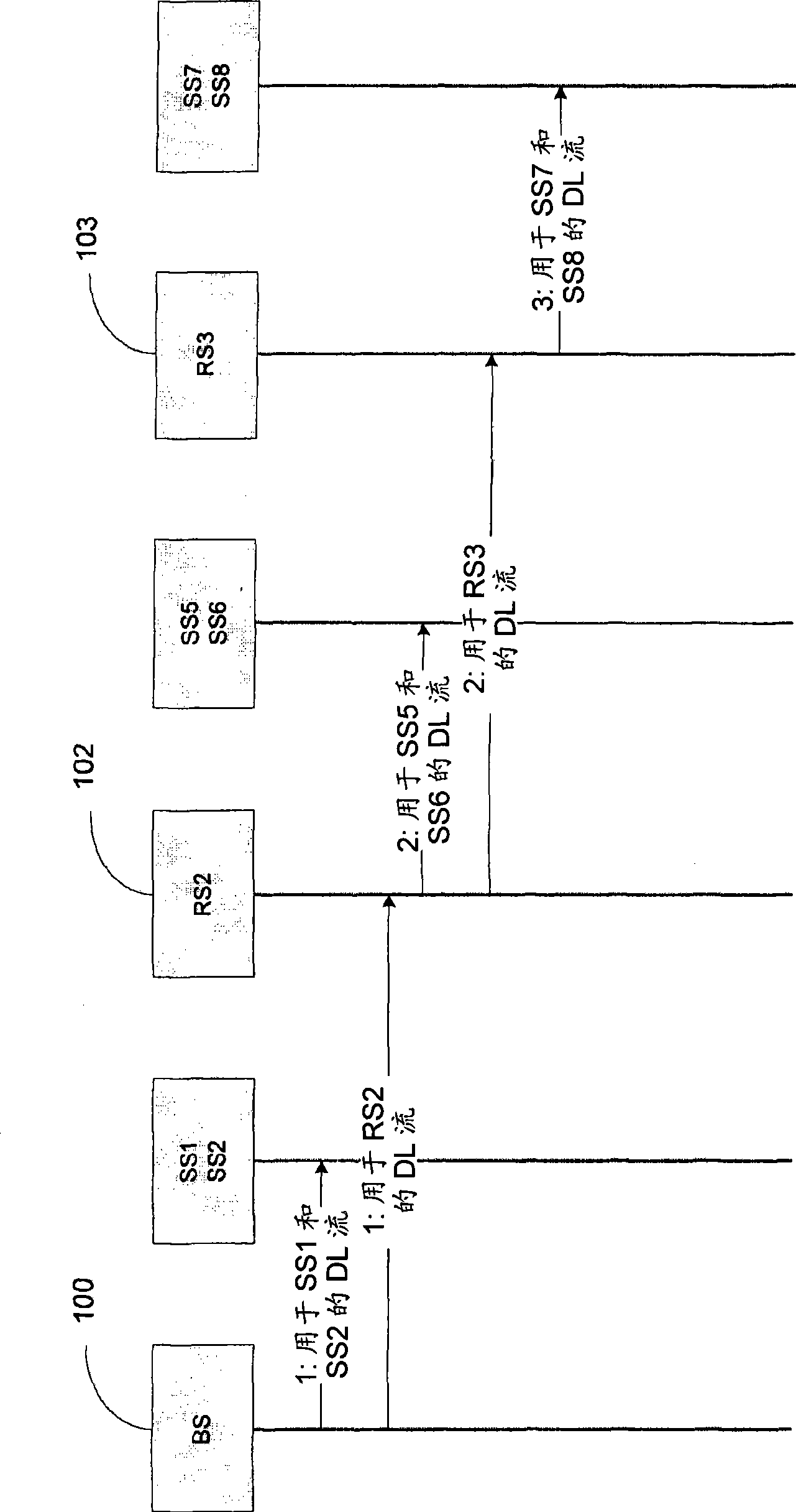
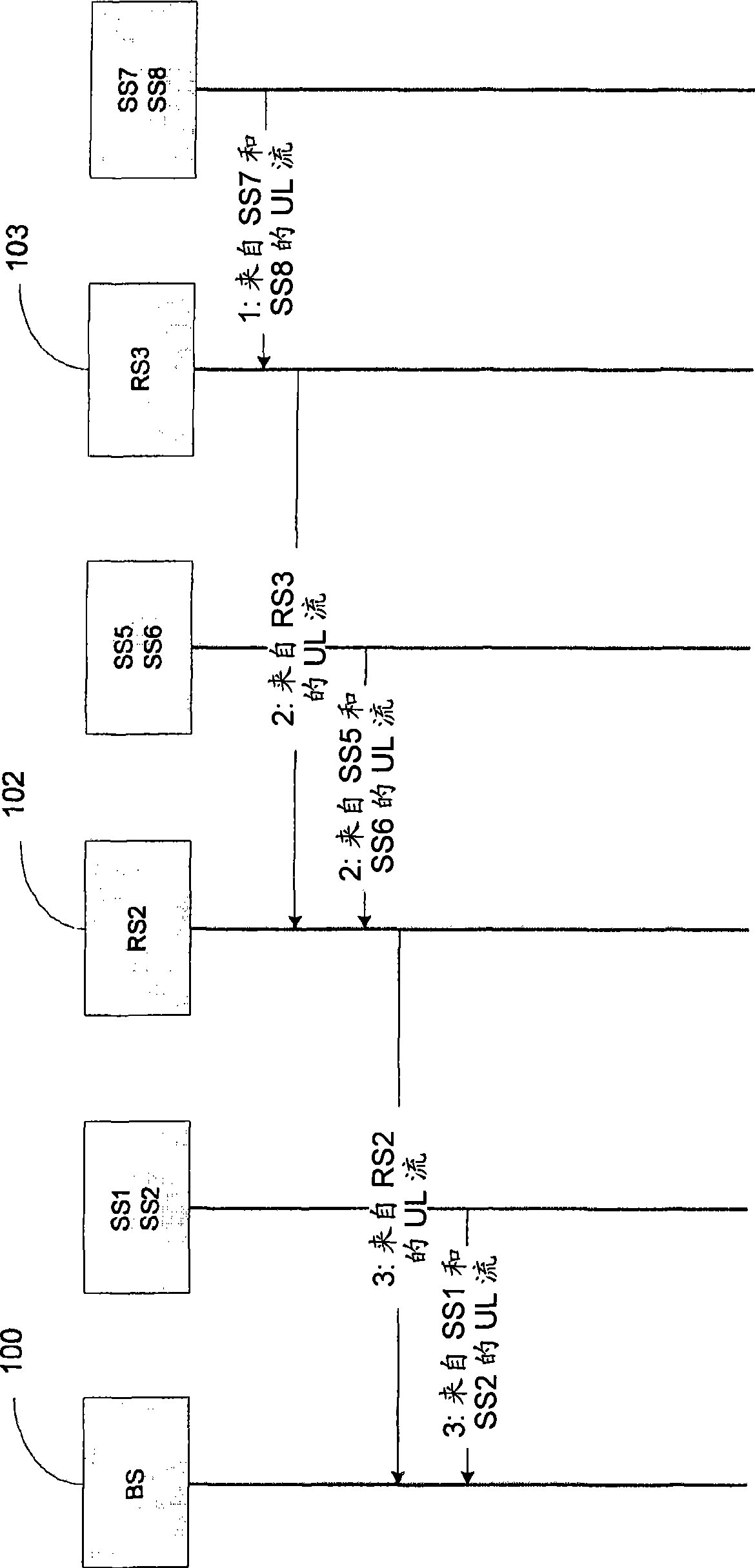
[0017] The specification of the present application describes, inter alia, embodiments of systems and techniques for scheduling the wireless transmission of data blocks between a base station (BS) and one or more relay stations (RS). The scheduling may be based on one or more factors (...


PUM


Abstract

The present invention discloses implementations of systems and techniques for scheduling wireless transmission of data blocks between a base station (BS) and one or more relay stations (RSs) in a wireless relay communication network.

Description

[0001] This application claims U.S. Provisional No. 60 / 845,950, entitled "Frame Structure For Multi-Hop Relay In Wireless Communications Systems," filed September 19, 2006 priority of the application, which is incorporated herein by reference as part of the specification of the present application. technical field [0002] The present application relates to wireless communication systems and techniques for wireless communication using one or more relay stations in addition to a base station. Background technique [0003] Wireless communication systems use electromagnetic waves to communicate with fixed and mobile wireless communication devices (eg, mobile wireless telephones and laptop computers with wireless communication cards) located within cells of the system's coverage area. A range or band of radio spectrum designated or allocated for wireless communication services or specific classes of wireless services may be divided into different radio carrier frequencies for ge...

Claims


Application Information

Patent Timeline
Patent Type & Authority Applications(China)
IPC IPC(8): H04B7/15H04W72/04H04W72/12H04W88/02H04W88/04H04W88/08
CPCH04W72/1263H04W84/047H04B7/2606H04B7/15542H04B7/005H04B7/15
Inventor 蔡思东
Owner ZTE (USA) INC
Why Eureka
Try Eureka