
Electric vacuum cleaner

A vacuum cleaner and electric technology, which is applied in the direction of vacuum cleaners, cleaning equipment, household appliances, etc., can solve the problems of limited movable range and difficult design, and achieve the effect of convenient operation

Inactive Publication Date: 2009-10-07
PANASONIC CORP
View PDF4 Cites 1 Cited by
  • Summary
  • Abstract
  • Description
  • Claims
  • Application Information

AI Technical Summary

Problems solved by technology

[0005] In addition, in the dust collection box with a buckle mechanism fixed to the vacuum cleaner body on the handle, although the convenience of use has been improved, the movable range is quite limited, and the locking part needs to be made into a fitting structure. Difficult Design Problems

Method used


Image

  • Electric vacuum cleaner
  • Electric vacuum cleaner
  • Electric vacuum cleaner

Examples


Embodiment Construction

[0020] An embodiment of the present invention will be described in detail below with reference to the accompanying drawings. At the same time, it should be pointed out that such embodiments do not limit the scope of the present invention.

[0021] (Example)

[0022] pass below Figure 1 ~ Figure 4 An electric vacuum cleaner in one embodiment of the present invention will be described in detail.

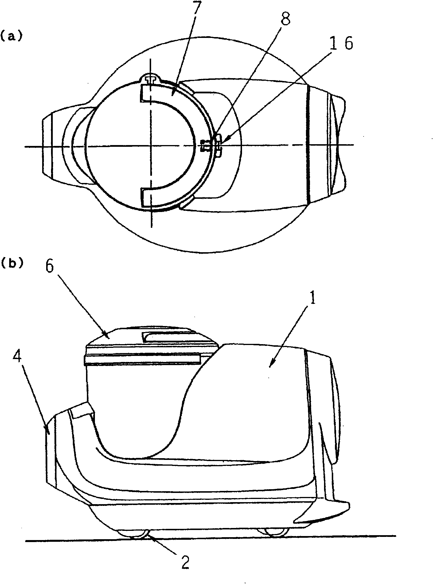
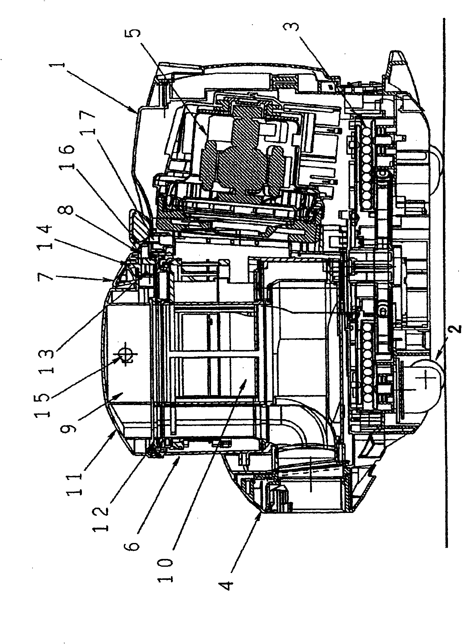
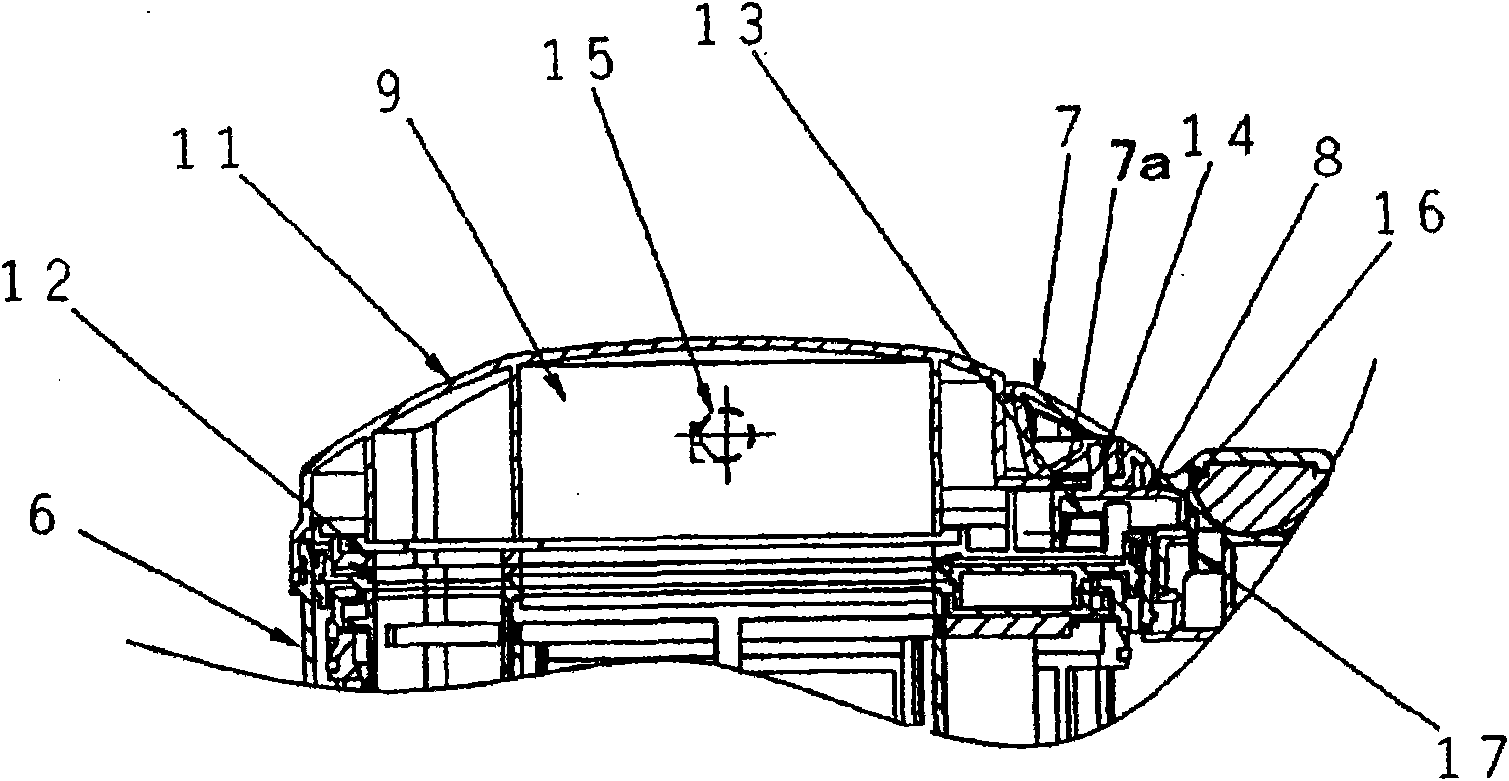
[0023] exist Figure 1 ~ Figure 4 middle, figure 1 (a) and figure 1 (b) is a top view and a side view showing the appearance of the vacuum cleaner body in this embodiment, figure 2 is a central sectional view of the electric vacuum cleaner, image 3 It is a partial cross-sectional view of the assembly and disassembly part of the dust collection box that constitutes the main feature of the present invention, the handle in the figure is in the storage position / the dust collection box is in a fixed state), Figure 4 It is also a partial cross-sectional view showing the assembly a...


PUM


Abstract

The present invention provides an electric vacuum cleaner capable of improving the convenience during mounting or dismounting of dust collection box, wherein, the dust collection box (6) is provided with a freely rotary handle (7) for conveying the dust collection box, and a freely sliding coupling shaft (8) for fixing the dust collection box in the vacuum cleaner body (1). On the other hand, a jogged section (16) for coupling shaft jogging is provided at one side of the vacuum cleaner body, the coupling shaft can be linked with the movement of the handle on the dust collection box, performing jogging or releasing jogging with the jogged section. When the handle is pulled up, the coupling shaft slides from the jogged section, only the dust collection box can be removed.

Description

technical field [0001] The invention relates to an electric vacuum cleaner with a detachable dust collecting box. Background technique [0002] The existing detachable dust box is respectively provided with: an operating part for connecting and fixing with the vacuum cleaner body, and a handle for carrying the dust box (for an example, refer to Japanese Patent Publication 2006- 61543). [0003] In addition, some of the handles on the dust collection box are also provided with a buckle mechanism for fixing with the body of the vacuum cleaner (for an example, refer to Japanese Patent Publication No. 2004-290339). [0004] However, in the structure in which the handling handle of the dust box as described above and the coupling shaft for fixing the dust box to the body of the vacuum cleaner move independently of each other, it is necessary to lift the handle with one hand when removing the dust box, and then use the The other hand performs the operation of uncoupling, which i...

Claims


Application Information

Patent Timeline
IPC IPC(8): A47L5/00
Inventor 黑木义贵仲本博司吉川达夫山口诚二
Owner PANASONIC CORP
Learn More