Lifting type conveyor

A lifting and conveying technology, which is used in transportation and packaging, walking bridge cranes, cranes, etc., can solve the problems of increased manufacturing costs, skewed relative positions, and increased weight of trucks, and can achieve stable handling and prevent relative. Rotation, anti-swing effect

Active Publication Date: 2009-10-07
NAKANISHI METAL WORKS CO LTD
View PDF5 Cites 17 Cited by
  • Summary
  • Abstract
  • Description
  • Claims
  • Application Information

AI Technical Summary

Problems solved by technology

[0004] However, the scheme of Patent Document 1 can restrain the swing in the direction parallel to the conveyance rail to a certain extent, but when the conveyance rail is curved, the inertial force to the left and right directions in the direction of travel will make the first and second The relative positions of the telescopic parts are skewed to each other. As a result, the lower frame also rotates, and in order to avoid this situation, the corresponding use of the first and second telescopic parts with larger widths will lead to an increase in the weight of the truck and lead to manufacturing problems. Increased cost, so there is room for improvement

Method used


Image

  • Lifting type conveyor
  • Lifting type conveyor
  • Lifting type conveyor

Examples


Embodiment Construction

[0025] Hereinafter, embodiments of the present invention will be described with reference to the drawings, but the present invention is not limited to the illustrated forms, and includes all embodiments that satisfy the requirements described in the claims.

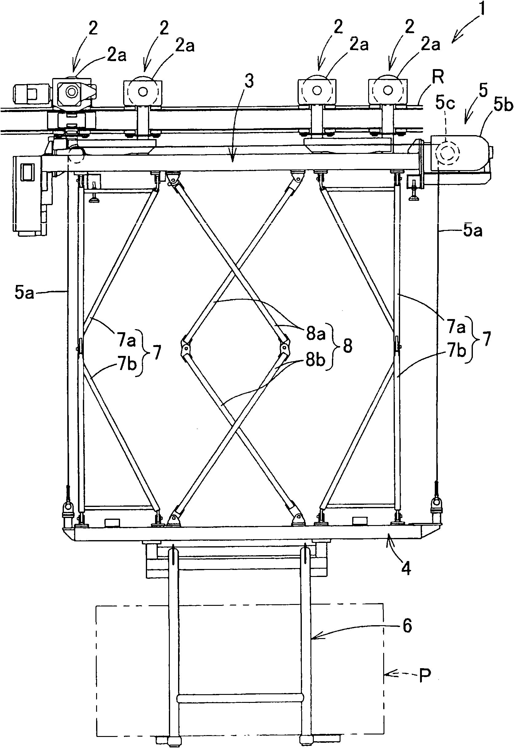
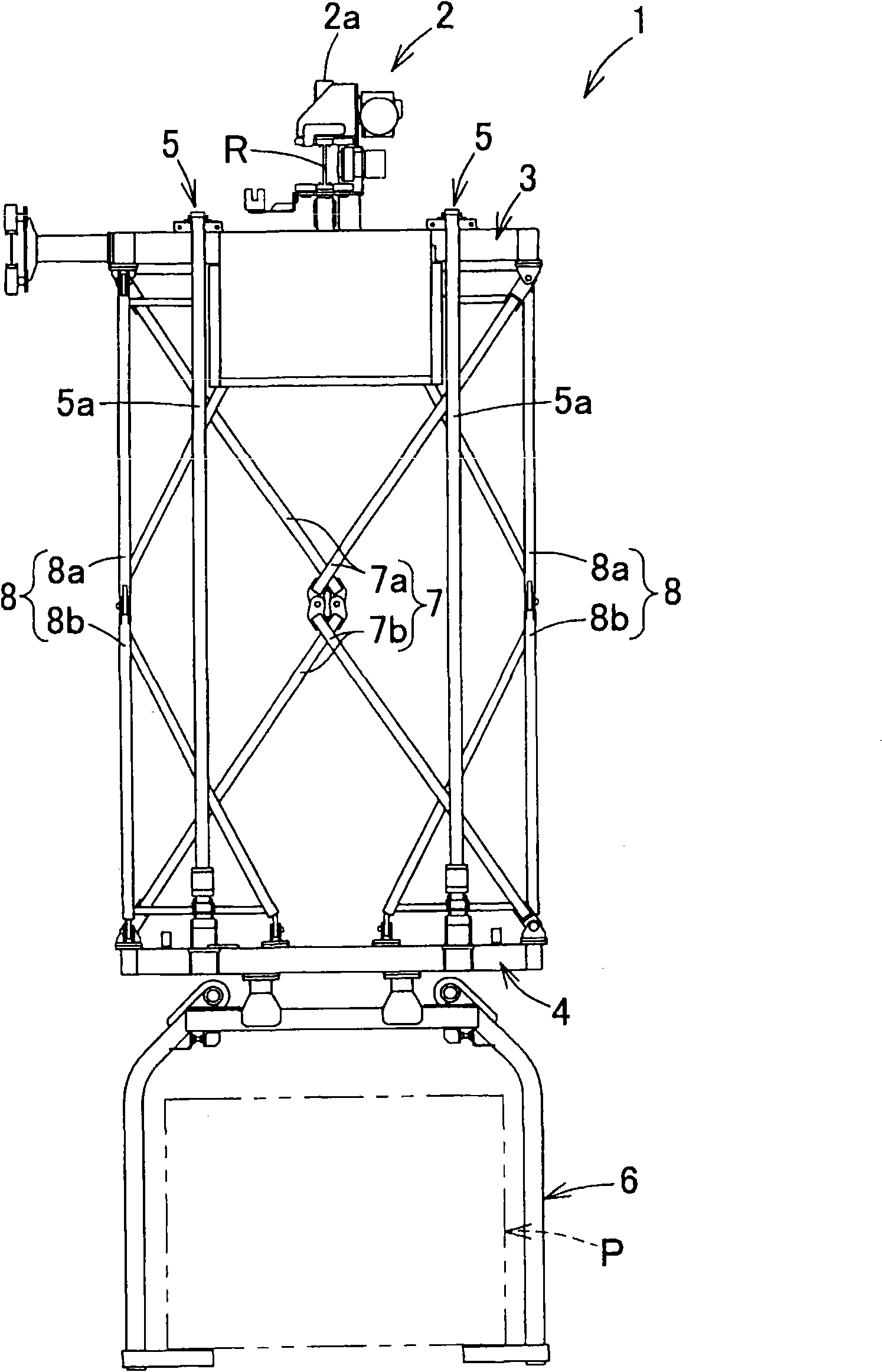
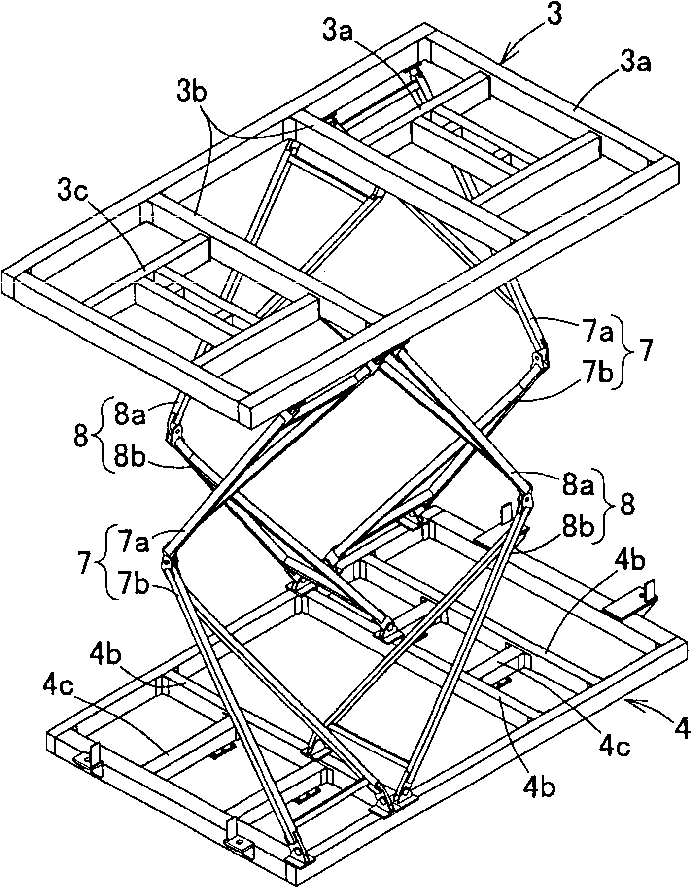
[0026] Figure 1 to Figure 5 It is an explanatory drawing which shows the structure of the elevating lift conveyor 1 of this embodiment. figure 1 It is a front view showing the state where the lower frame 4 of the lift conveyor 1 according to the present embodiment is in the lowermost position, figure 2 for the left view, image 3 It is a perspective view showing the structure of the first and second anti-sway frames 7, 8, Figure 4 It is a front view showing the state where the lower frame 4 of the lift conveyor 1 of this embodiment is at the uppermost position, Figure 5 It is a plan view showing the structure below the upper frame 3 in which the lower frame 4 is in the uppermost position.

[0027] Such as figure ...


PUM


Abstract

The invention provides a lifting type conveyer (1) capable of preventing the sway of the load (P) and safely conveying the load (P) and increasing the lifting range of the load (P). The lifting type conveyer (1) comprises an upper frame (3) suspended on a carriage running on a conveying trail ( R ), a lower frame (4) liftably mounted below the upper frame (3) with a hanging frame (6); a first sway prevention frame (7) with a first upper frame (7a) and a first lower frame (7b) and capable of correspondingly folding or extending along with the lifting of the lower frame (4), wherein the first upper frame (7a) is approximately of upside-down triangle and in axle suspension on the upper frame (3) and the first lower frame (7b) is longitudinal symmetry with the first upper frame (7a) and the lower end of the first upper frame is in axle connection with the upper end; and a second sway prevention frame (8) longitudinal symmetry with the first sway prevention frame (7) and vertically extending on the horizontal plane opposite to the upper border of the first upper frame (7a).

Description

technical field [0001] The present invention relates to an elevating type hoisting conveyor (オバヘツツドオリア) that moves along a conveying rail, and more particularly to an elevating type hoisting conveyor that can be safely transported by avoiding large swings of the load being transported relative to the trolley Drop off. Background technique [0002] Conventionally, in order to effectively suppress the swinging of the conveyed object, a conveying device has been proposed, which includes: a trolley engaged with a conveying rail, an upper frame suspended by the trolley, and a lower frame arranged below the upper frame to move up and down. The lifting device, the carrier sling set on the lower frame, the first telescopic member formed by rotatably connecting the upper end to the horizontal shaft at the front of the upper frame and rotatably connecting the lower end to the horizontal shaft at the rear of the lower frame, and the upper The horizontal shaft at the rear of the frame ...

Claims


Application Information

Patent Timeline
Patent Type & Authority Applications(China)
IPC IPC(8): B66C17/00B66C13/06
Inventor J·鲁伊斯
Owner NAKANISHI METAL WORKS CO LTD
Why Eureka
Try Eureka