
Image position adjustment device and optical device

An adjustment device and adjustment mechanism technology, applied in optics, optical components, installation, etc., can solve problems such as increased rotation, heat-related, large-scale structures, etc., to achieve the effect of eliminating astigmatism

Active Publication Date: 2009-10-07
DAINIPPON SCREEN MTG CO LTD
View PDF8 Cites 17 Cited by
  • Summary
  • Abstract
  • Description
  • Claims
  • Application Information

AI Technical Summary

Problems solved by technology

[0008] However, in 1., there is the following problem: if a relatively thick parallel plate is used to obtain the desired offset, the magnitude (absolute value) and variation of the astigmatism caused by the rotation of the parallel plate will be large
If the parallel plate is made thinner in consideration of this point, the amount of rotation required will increase correspondingly, so there is a problem that the device itself will become larger.
In addition, in 2., it is necessary to move the entire optical system, so if the drive system is also included, it becomes a large-scale structure, and space for accommodating movable parts in the shift direction is required.
Moreover, there are also problems that the positioning accuracy decreases with the movement of the entire optical system and problems related to reproducibility and heat
Furthermore, 3. has the same problem as 2. In particular, when the object arranged on the upstream side is a variable object (mask or aperture (aperture), etc.) or an object that generates a pattern electrically, will become a massive structure

Method used


Image

  • Image position adjustment device and optical device
  • Image position adjustment device and optical device
  • Image position adjustment device and optical device

Examples


no. 1 approach

[0039]

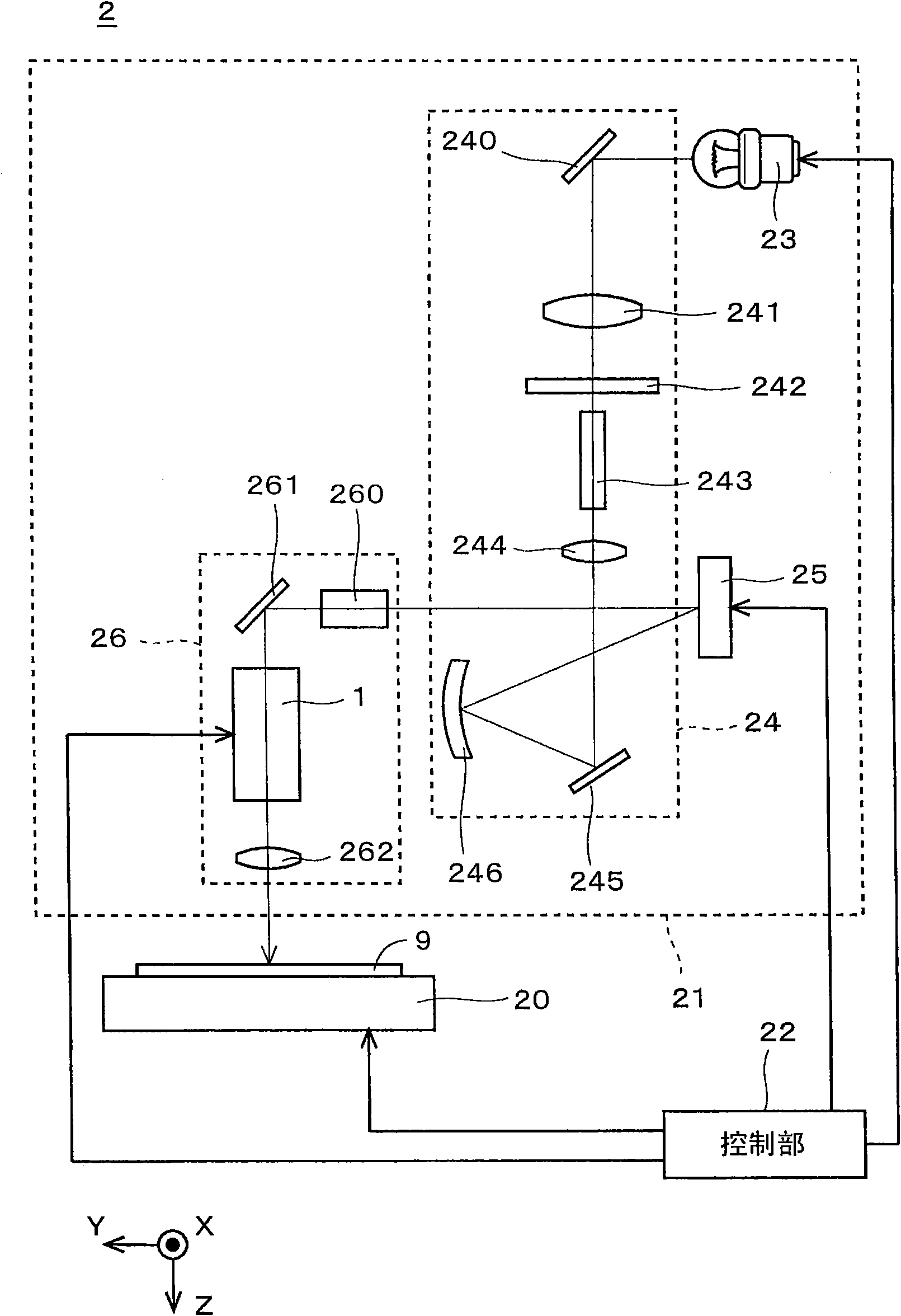
[0040] figure 1 It is a figure which shows the optical device 2 of the invention. In addition, in the following description, as figure 1 The X, Y, and Z axes are defined as shown. However, these directions are defined to facilitate grasping of the positional relationship, and are not intended to limit the respective directions described below. The same applies to the following figures.

[0041] The optical device 2 is an exposure device and includes a movable stage 20 , an exposure head 21 , and a control unit 22 for exposing a fine pattern (image) on the substrate 9 supported by the movable stage 20 . That is, the upper surface of the substrate 9 corresponds to the image plane of the optical device 2 .

[0042] The upper surface of the movable stage 20 is processed into a horizontal plane, and has a function of holding the substrate 9 in a horizontal posture. The movable stage 20 is sucked through a suction port (not shown), thereby sucking the lower surface o...

no. 2 approach

[0112] The optical device 2 according to the first embodiment includes one image position adjustment device 1, but the device into which the image position adjustment device 1 can be incorporated is not limited to such a device.

[0113] Figure 7 It is a figure which shows the optical device 3 of 2nd Embodiment.

[0114]The optical device 3 includes a base 30 serving as a base of the structure of the optical device 3 , a frame 31 of a bridge structure spanning the upper surface of the base 30 , and a holding portion 32 for holding the substrate 9 .

[0115] The holding unit 32 includes a stage 320, a first plate 321, and a second plate 322, and has a function of holding the substrate 9, which is an object to be processed, in the optical device 3 in a predetermined posture.

[0116] The upper surface of the stage 320 is set to be a horizontal plane, and the substrate 9 is held in a horizontal posture by suction through a suction port (not shown) to suck the substrate 9 . A s...

no. 3 approach

[0133] The image position adjustment device 1 of the above-described embodiment can adjust only the position of the image in the X-axis direction by adjusting the position of the second wedge prism 14 in the Z-axis direction by the adjustment mechanism 11 . However, other various states can also be adjusted by providing another drive mechanism in the image position adjusting device 1 .

[0134] Figure 10 The figure which shows the structure of the image position adjustment apparatus 1a of 3rd Embodiment. The image position adjustment device 1 a is different from the image position adjustment device 1 of the above-described embodiment in that the image position adjustment device 1 a includes a first rotation mechanism 15 , a second rotation mechanism 16 , and a third rotation mechanism 17 .

[0135] The first rotation mechanism 15 is a mechanism that rotates the optical system 10 around the Y axis. The Y-axis is an axis perpendicular to the X-axis and the Z-axis, respectivel...


PUM


Abstract

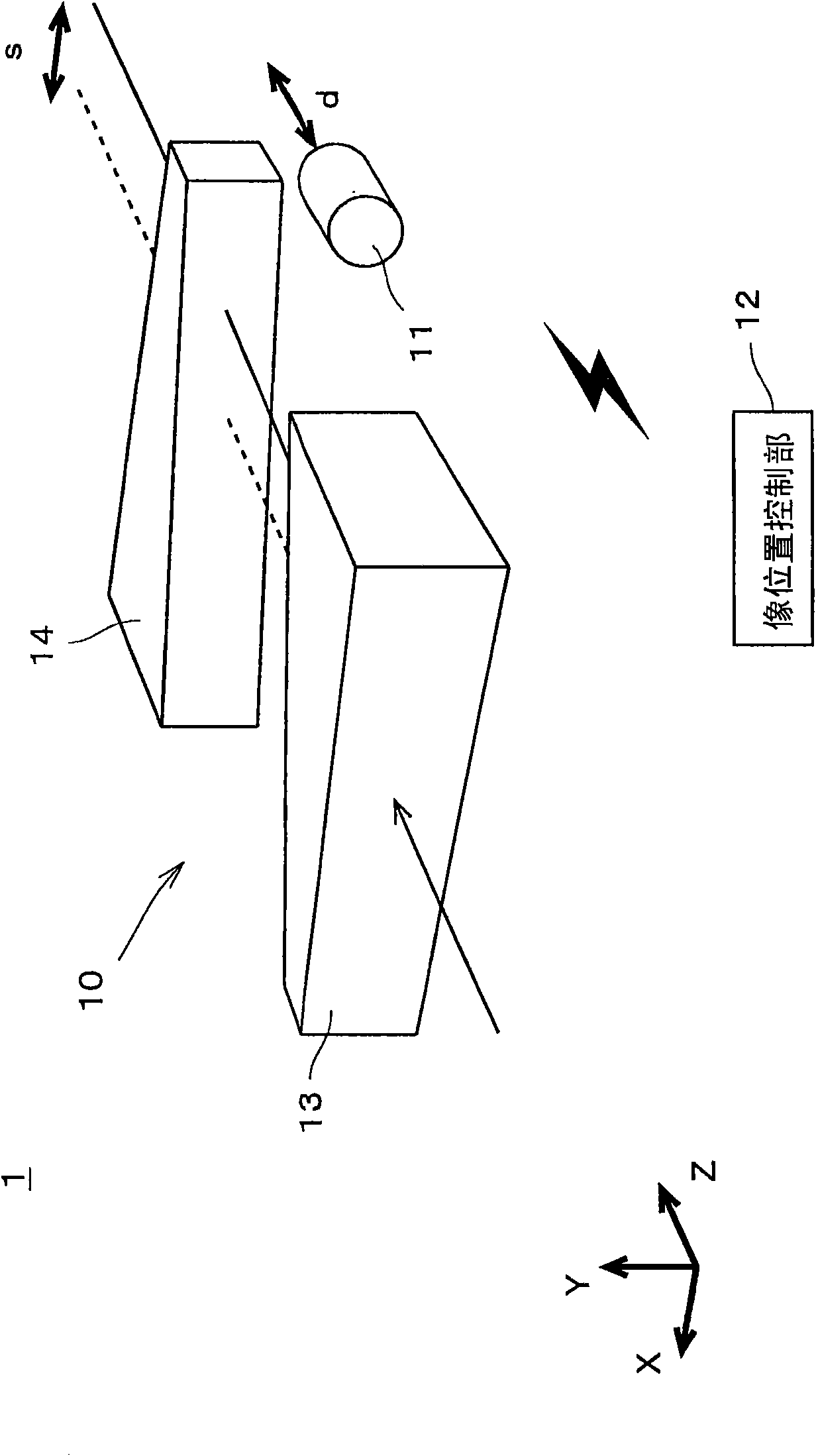
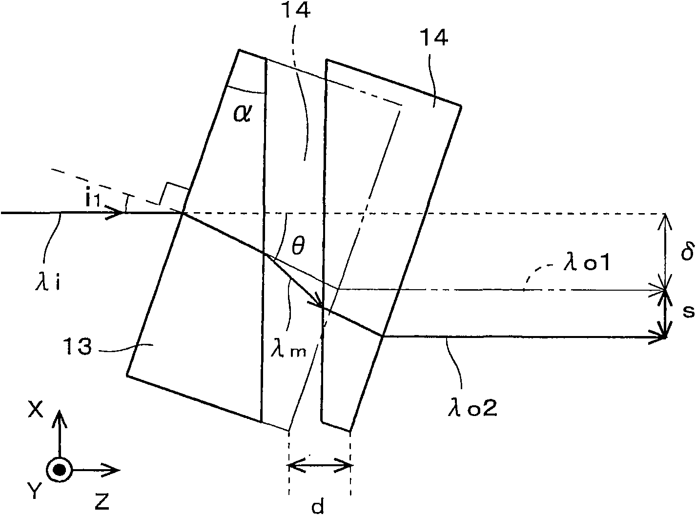
Provided is an image position adjustment device and an optical device, capable of shifting the image arbitrarily and compactly with a high precision without infection of the optical performance. the image position adjustment device (1) for shifting the image on an image surface is provided with an adjustment mechanism (11), a first wedge-shaped prism (13) and a second wedge-shaped prism (14). Thefirst wedge-shaped prism (13) is fixed that an incident light has a prescribed incidence angle, and the second wedge-shaped prism (14) is arranged in an opposition direction, such that the second wedge-shaped prism (14) is opposite with the first wedge-shaped prism (13). By means of moving the second wedge-shaped prism (14) in a Z axis direction (optical axis direction), a relative distance between the first and the second wedge-shaped prisms (13, 14) is altered, so as to adjust an offset on the image surface in a X axis direction.

Description

technical field [0001] The present invention relates to a technique for shifting an image on an image plane in a one-dimensional direction (offset direction). Background technique [0002] In an imaging optical system used in an exposure apparatus, a drawing apparatus, or the like, it may be necessary to shift the image position on the image plane by an arbitrary distance in the one-dimensional direction. Such cases are, for example, in a drawing apparatus that simultaneously exposes a large substrate by using a plurality of optical systems, it is necessary to accurately match the pitches between the plurality of optical systems, and in the process of performing multiple exposures, in order to It is necessary to draw the next pattern correctly on the base pattern which changes by shrinkage of a board|substrate, etc., and it is the case where the drawing pitch must be matched, etc. [0003] Therefore, various mechanisms for shifting the image position have been proposed so f...

Claims


Application Information

Patent Timeline
IPC IPC(8): G02B7/18G02B27/00
Inventor 北村藤和上山宪司
Owner DAINIPPON SCREEN MTG CO LTD
Learn More