Light scanning unit, image forming apparatus employing the same and light scanning methods

A technology of optical scanning and light source unit, which is applied in the field of optical scanning, can solve the problem that it is difficult to increase the oscillation angle of the torsional oscillator, and achieve the effect of reduced manufacturing size and easy optical design

Inactive Publication Date: 2009-10-07
SAMSUNG ELECTRONICS CO LTD
View PDF2 Cites 7 Cited by
  • Summary
  • Abstract
  • Description
  • Claims
  • Application Information

AI Technical Summary

Problems solved by technology

However, it is difficult to increase the oscillation angle of the torsional oscillator due to the instrumental limitations of the torsional oscillator

Method used


Image

  • Light scanning unit, image forming apparatus employing the same and light scanning methods
  • Light scanning unit, image forming apparatus employing the same and light scanning methods
  • Light scanning unit, image forming apparatus employing the same and light scanning methods

Examples


Embodiment Construction

[0045] Reference will now be made in detail to embodiments of the invention, examples of which are illustrated in the accompanying drawings, wherein like reference numerals refer to like parts. Although the embodiments have been described in structural and component detail to facilitate a comprehensive understanding of the various uses and advantages of the embodiments, it should be clear that the embodiments may be practiced without those specific details. Also, known functions or constructions are not described in detail to avoid obscuring the description with unnecessary detail. It should also be noted that in the drawings, the dimensions of features are not true to scale and may be exaggerated for better understanding.

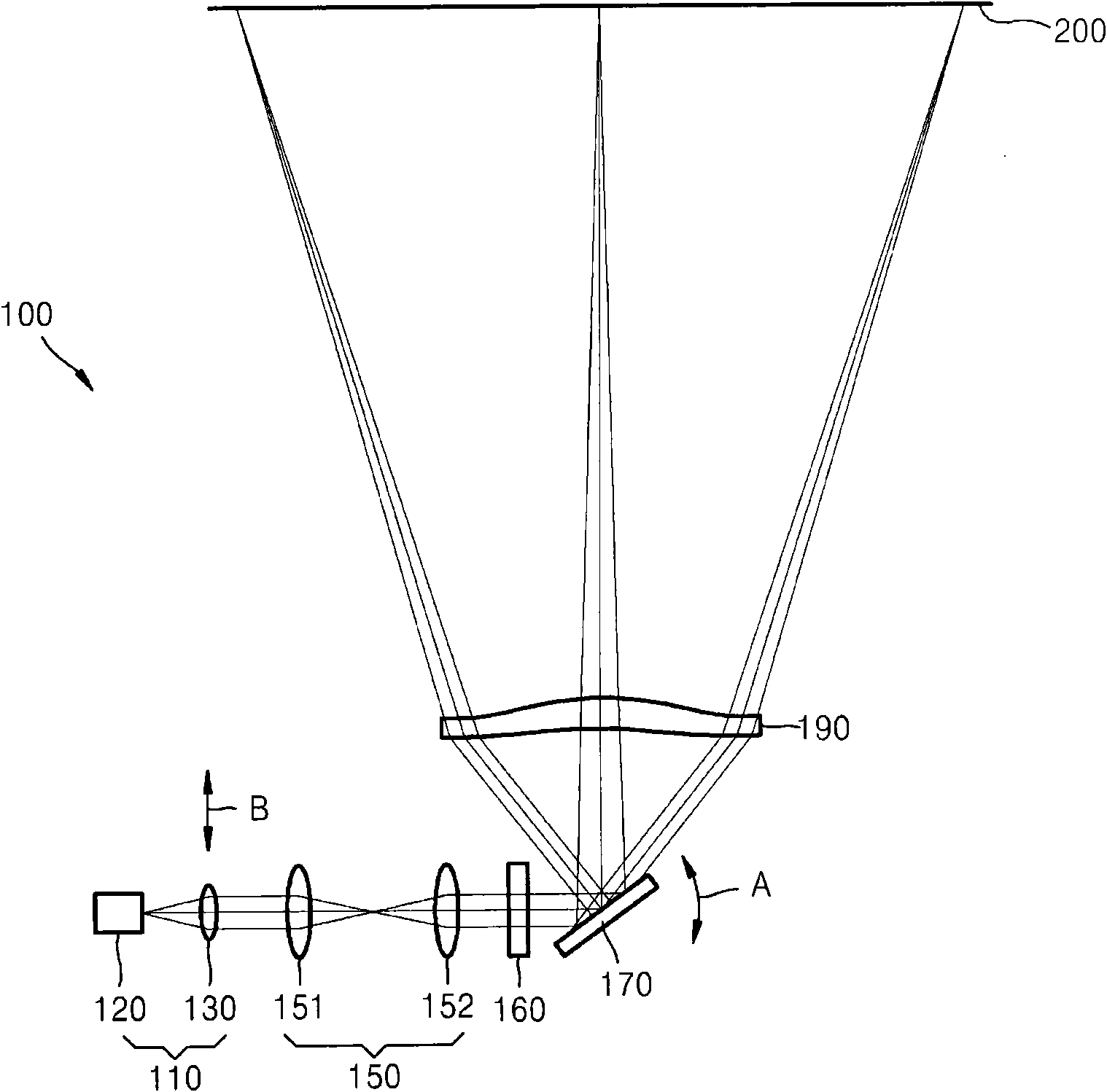
[0046] figure 1 The optical configuration of the light scanning unit 100 according to the embodiment of the present invention is shown.

[0047] refer to figure 1 , the light scanning unit 100 may include: a light source unit 110 emitting a collimated b...


PUM


Abstract

A light scanning unit including a light source unit for emitting a collimated light beam, and a beam deflector for deflecting and scanning the collimated light beam and having a mirror surface controllable to oscillate, a light scanning method and an image forming apparatus employing the light scanning unit are disclosed. The light source unit may be made to oscillate synchronously with the oscillation of the beam deflector so that the incident angle of the collimated light beam on the beam deflector changes in synchronization with the oscillation of the beam deflector, thereby allowing an increase of the maximum deflection angle of the light beam deflected and scanned by the beam deflector.

Description

[0001] This application claims the benefit of Korean Patent Application No. 10-2008-0031713 filed with the Korean Intellectual Property Office on Apr. 4, 2008, the entire disclosure of which is hereby incorporated by reference. technical field [0002] The present invention relates to an optical scanning unit, an optical scanning method, and an imaging device using the optical scanning unit, and more particularly, to an optical scanning unit that creates sinusoidal oscillation using a torsional oscillator including a mirror as an optical deflector, An imaging device using the optical scanning unit and an optical scanning method used by the imaging device. Background technique [0003] A light scanning unit is an optical device that scans light emitted from a light source onto an exposed surface. The light scanning unit is used in image forming apparatuses (for example, copiers, printers, facsimile machines, etc.) that utilize electrophotography to obtain images on printing p...

Claims


Application Information

Patent Timeline
Patent Type & Authority Applications(China)
IPC IPC(8): G02B26/10G03G15/04G03G15/00H04N1/113
CPCG02B26/105G03G15/04
Inventor 崔钟喆崔祐硕
Owner SAMSUNG ELECTRONICS CO LTD
Why Eureka
Try Eureka