
Control mechanism of multipolar electrical switch

A technology of control mechanism and electrical switch, which is applied to the power device inside the switch, the switch where the bridge contact is not connected, etc., which can solve the problems of complicated parts layout and increase of manufacturing cost, etc.

Inactive Publication Date: 2009-10-07
BOMIL AB
View PDF5 Cites 2 Cited by
  • Summary
  • Abstract
  • Description
  • Claims
  • Application Information

AI Technical Summary

Problems solved by technology

[0007] Of course, such mechanisms include fewer parts than prior art mechanisms, which consist of too many parts whose arrangement is very complicated, which increases its manufacturing cost

Method used


Image

  • Control mechanism of multipolar electrical switch
  • Control mechanism of multipolar electrical switch
  • Control mechanism of multipolar electrical switch

Examples


Embodiment Construction

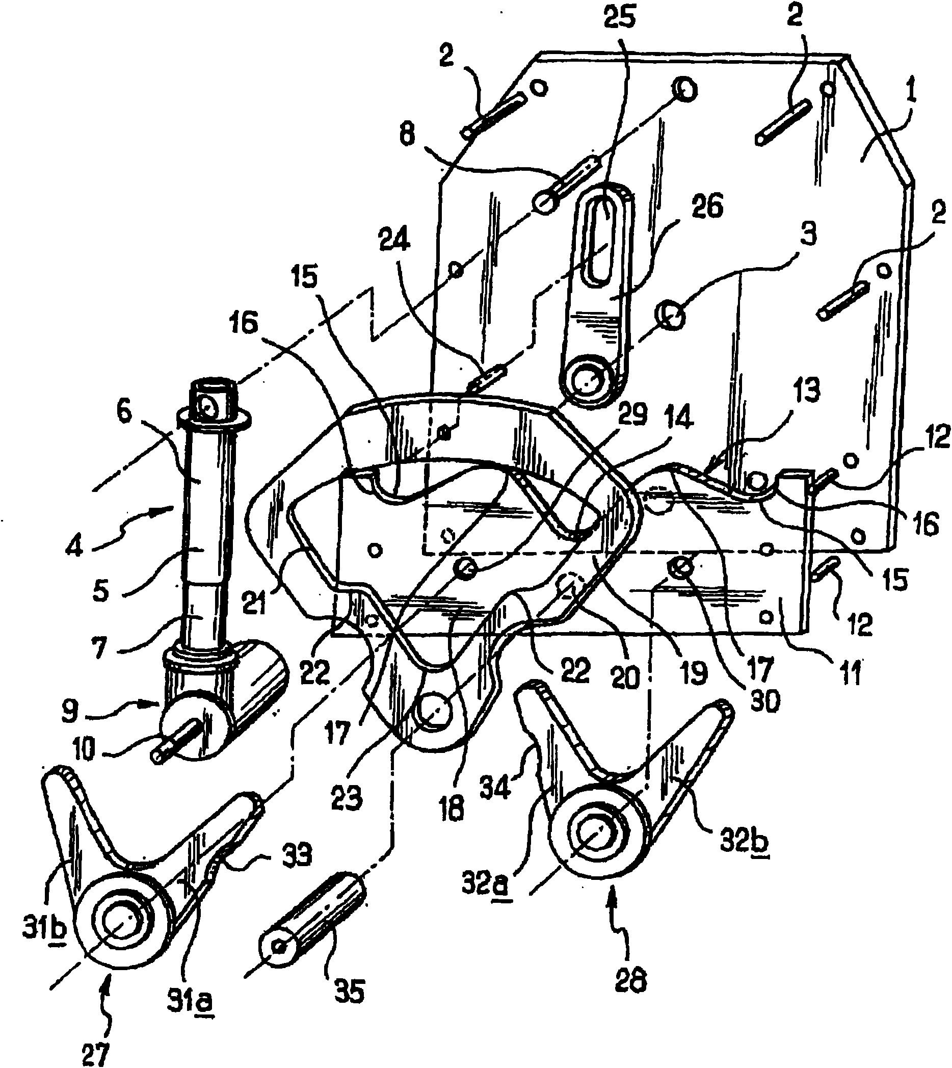
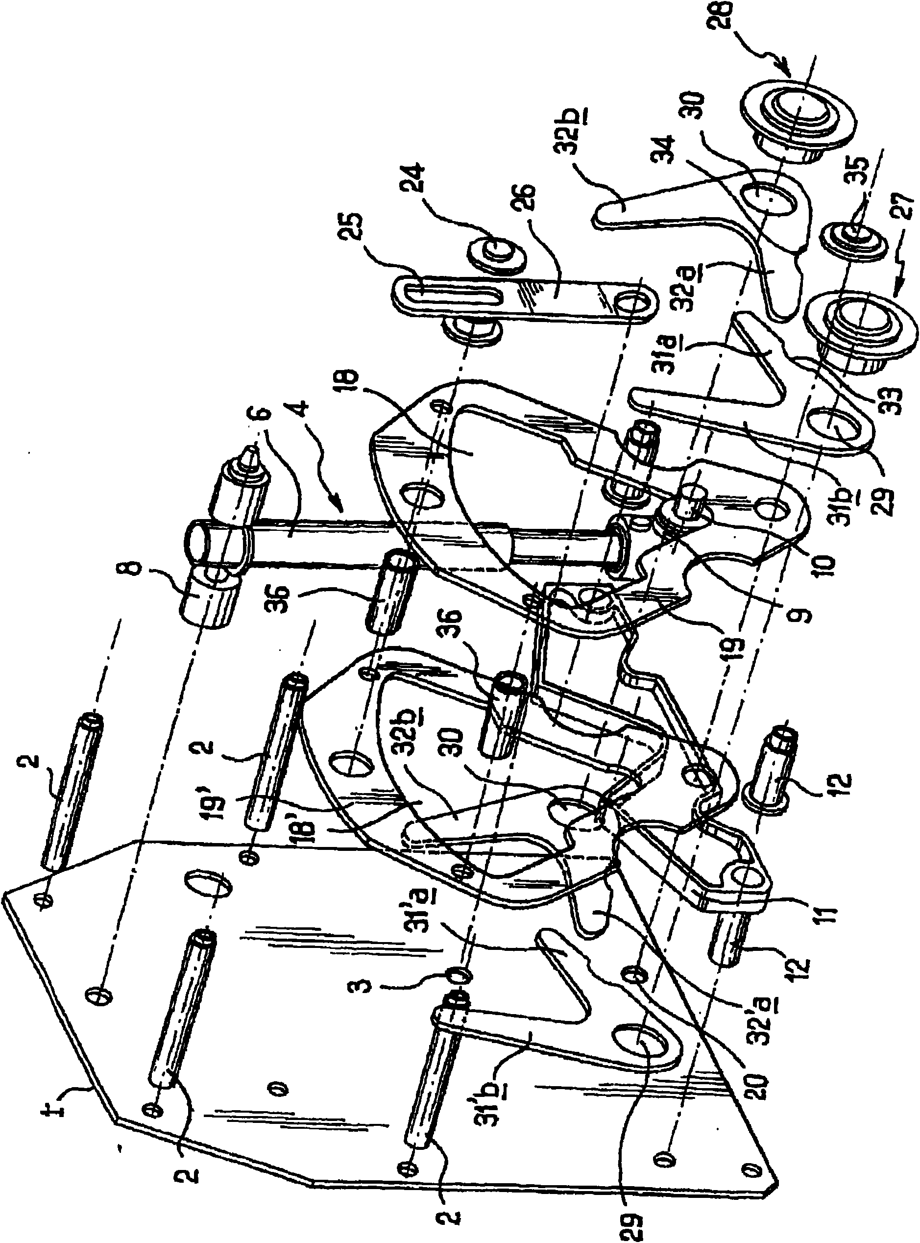
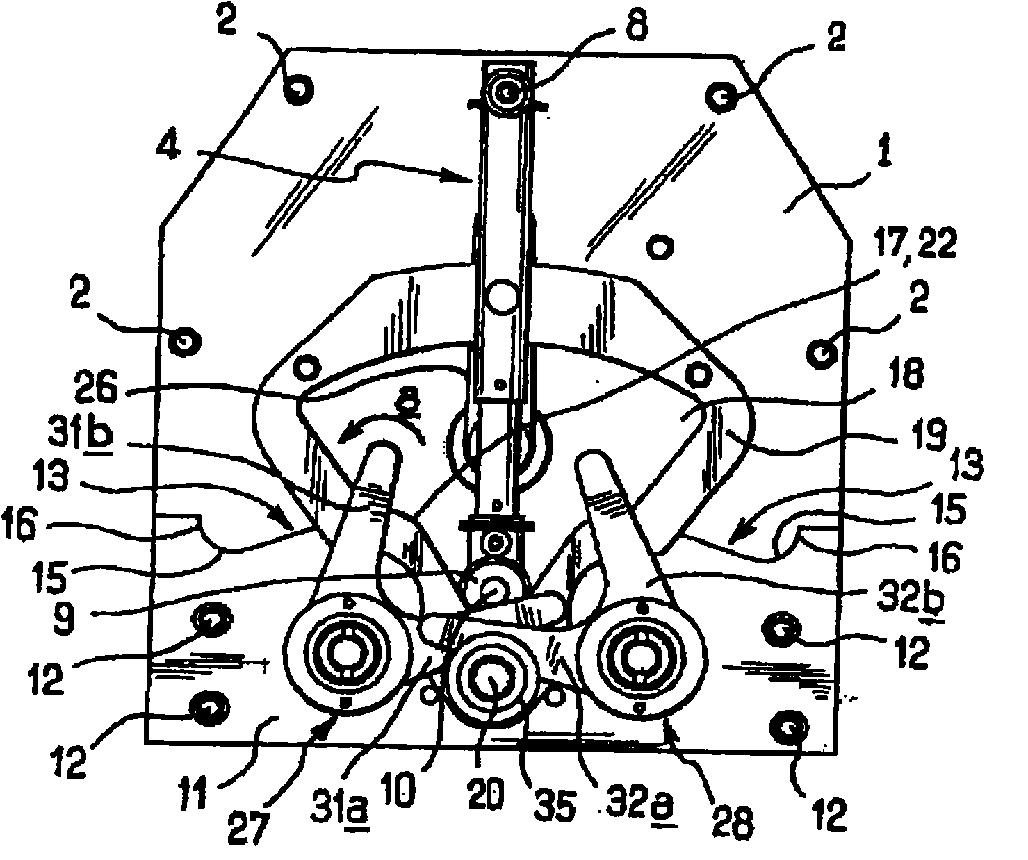
[0016] refer to figure 1 with image 3 , such as the multipole switch described in French patent 2 606 209, the control mechanism of a multipole switch consists of a pair of vertical side plates 1 forming supports and separated by transverse links 2, only one of which is shown in the figure Side panel 1, the side panel at the back. The rear side plate 1 comprises, in its plane of symmetry corresponding to the sagittal plane of said side plate 1 , an output shaft 3 (not shown in the figure) for actuating a multipolar electric switch, which can optionally be placed in 3 Stable positions, that is, the switch's open position, closed position and ground position. The mechanism according to the invention comprises a single spring accumulator 4 consisting of a helical spring 5 placed in a cylinder 6 in which a piston 7 slides and from which Protruding, the helical spring 5 is supported by the bottom of the cylinder 6 and one end of the piston 5, respectively. The free end of the ...


PUM


Abstract

The invention relates to a control mechanism of a multipolar electrical switch of output shaft type. An output shaft (3) is provided with a contact which is operated to be selectively arranged in such three stable positions as a switch-on position, a switch-off position and a grounding position. The overturn type control mechanism comprises a single spring accumulator (4) and two control devices (27) and (28), wherein the first tail end of the single spring accumulator (4) is hinged on vertical side plates (1) around a shaft (8) parallel to the output shaft (3), and the other end is provided with a cylindrical pulley (9) which is freely rotatably mounted around a shaft (10) of the output shaft (3), cooperatively acts with retrieval mechanisms (13), (19, (24), (25) and (26) driving the output shaft (3) to rotate and cooperatively acts with at least two radial pallets (31a) and (31b) or (32a) and (32b) connected with the control devices (27) and (28), and rotary shafts of the radial pallets (31a) and (31b) or (32a) and (32b) are parallel to the extension of the output shaft (3).

Description

technical field [0001] The present invention relates to a control mechanism for a multi-pole electrical switch having an output shaft with contacts and actuating them, and the output shaft can be selectively placed in three stable positions: open switch position , the position of the closed switch and the position of the ground, the main shaft is driven to rotate by cooperating with the first close and open control device retrieval mechanism of the switch on the one hand, and with the second control device of the ground on the other hand. Background technique [0002] In the field of high voltage multi-pole switching control mechanisms, mechanisms are known which comprise two independent control means, one means for closing and opening the switch and the other means for earthing. Each of these tumbler devices has a spring and interlock system that inhibits various misoperations, especially the operation of grounding the device when the switch is closed. The so-called flip-t...

Claims


Application Information

Patent Timeline
IPC IPC(8): H01H3/30H01H31/16
Inventor J-L·格里莫V·费洛塔德J-L·格里莫
Owner BOMIL AB
Learn More