
Valve unit with axial pressure medium inlet

A pressure medium, axial technology, applied in the direction of control valve, valve device, functional valve type, etc., can solve the problems of hindering the movement of the valve piston and the intrusion of dirt particles, and achieve the effect of simple design scheme and cheap design scheme

Inactive Publication Date: 2018-05-22
SCHAEFFLER TECH AG & CO KG
View PDF10 Cites 0 Cited by
  • Summary
  • Abstract
  • Description
  • Claims
  • Application Information

AI Technical Summary

Problems solved by technology

[0003] The problem is that dirt particles can penetrate into the control unit or the valve unit and block or block the movement of the valve piston in the valve housing
[0004] In addition, there is the problem that pressure medium can unintentionally flow back from the control device or the valve unit, or that the lines and the adjustment chambers in the camshaft adjuster lose control, resulting in unintentional adjustment of the camshaft adjuster of the internal combustion engine or of the transmission. other forms of regulation

Method used


Image

  • Valve unit with axial pressure medium inlet
  • Valve unit with axial pressure medium inlet
  • Valve unit with axial pressure medium inlet

Examples


Embodiment Construction

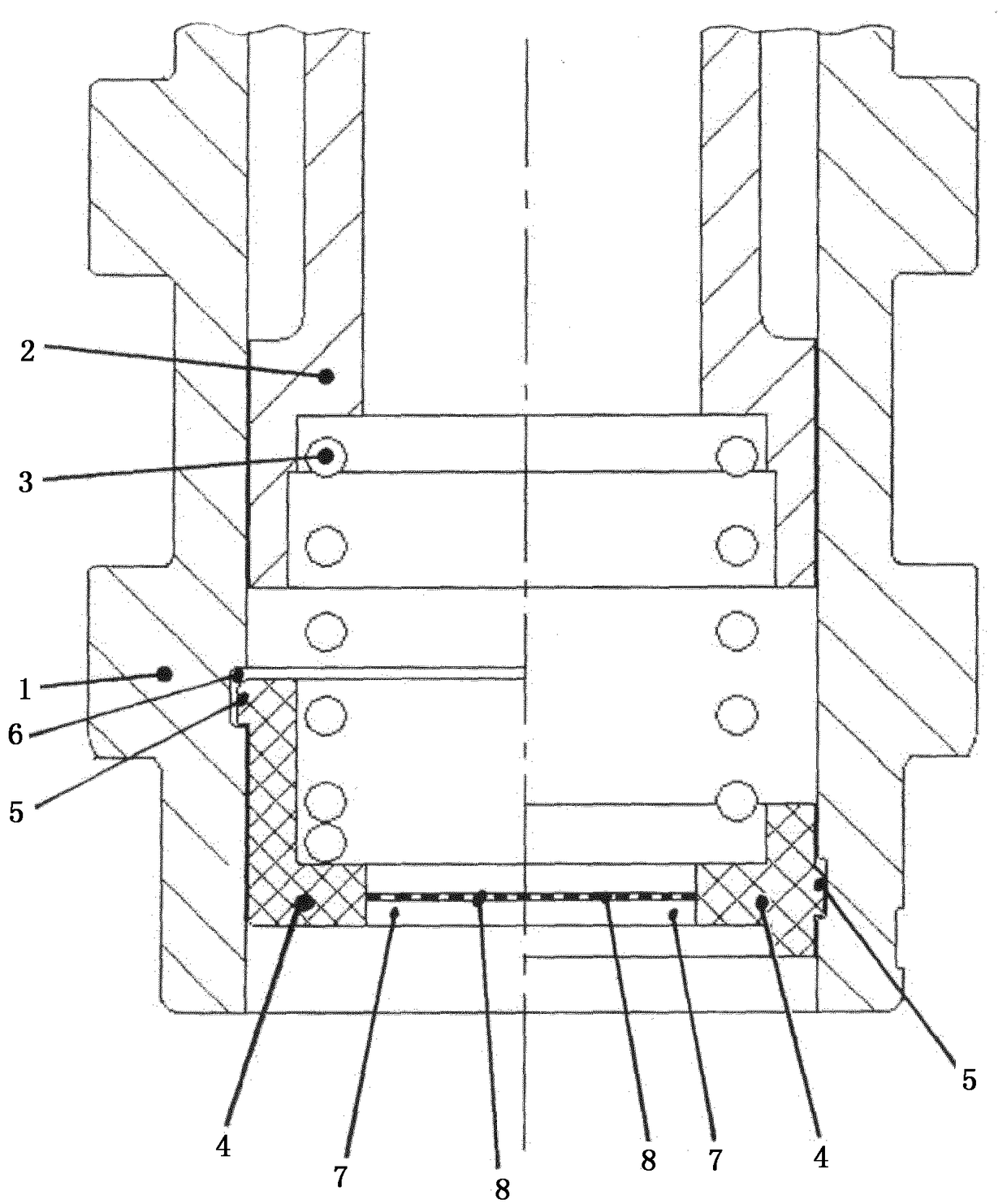
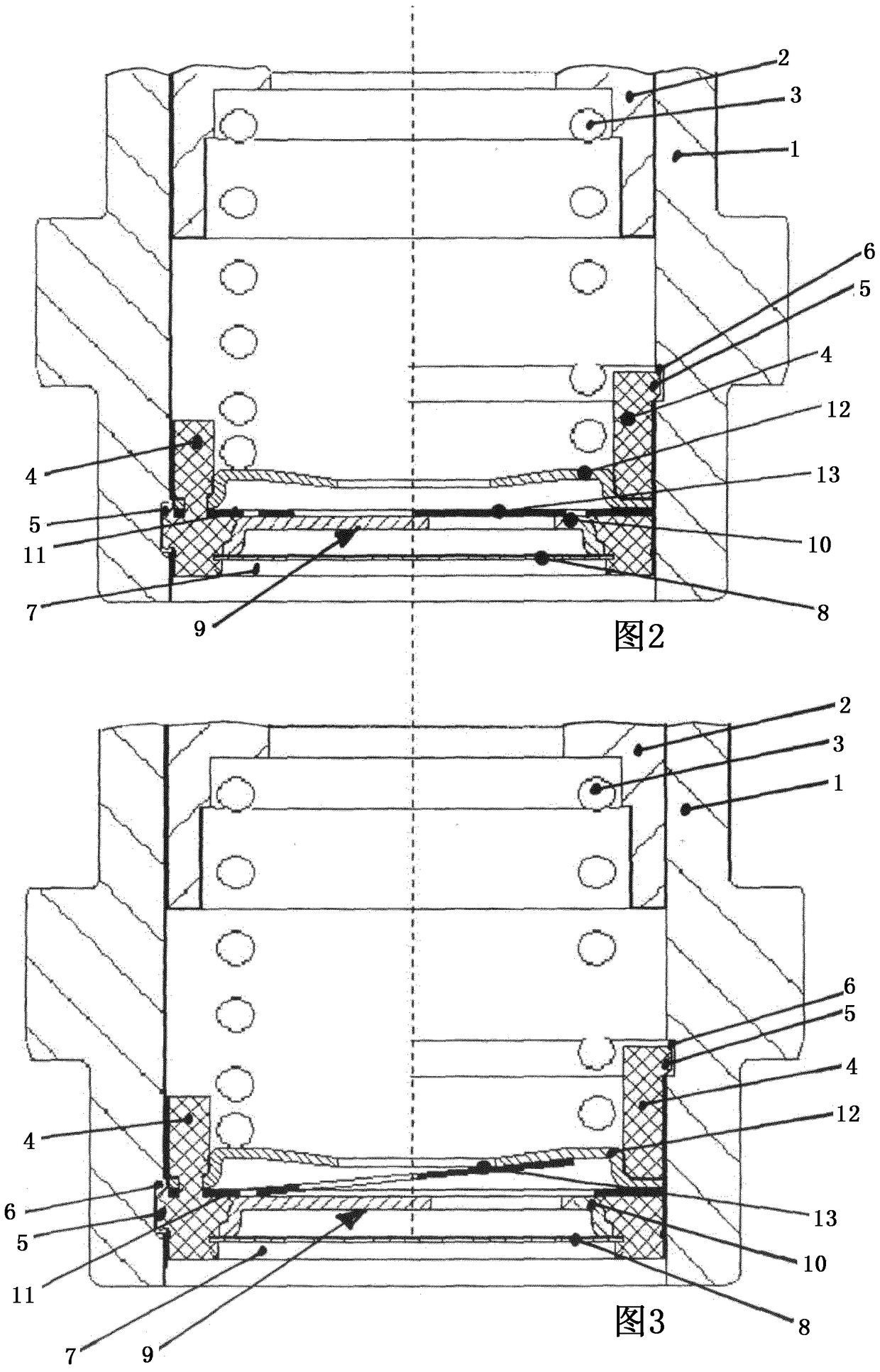
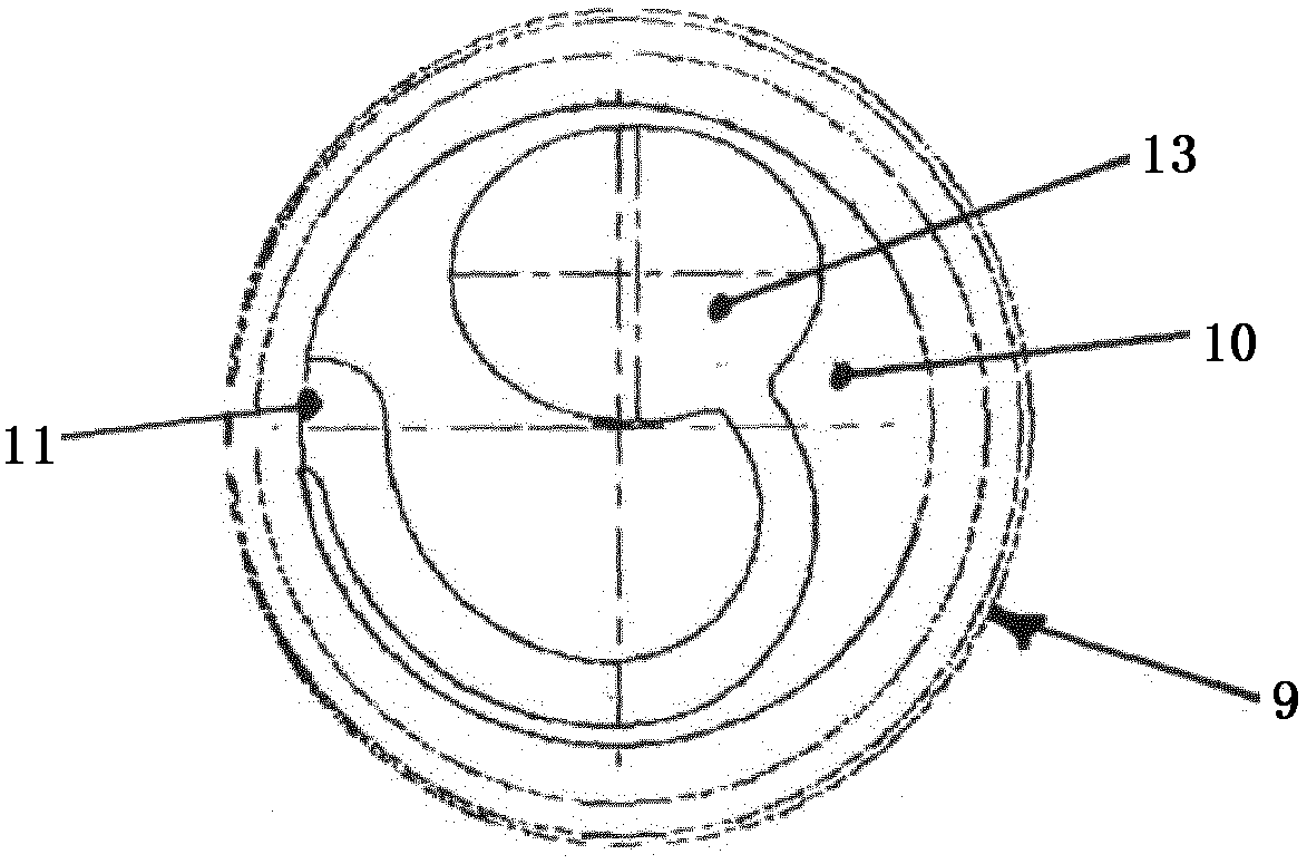
[0022] exist Figure 1 to Figure 5 shows in detail generally the valve housing designated 1 in which the control piston 2 is arranged and designed to be axially displaceable. The control piston 2 is operatively connected to a spring 3 supported on a spring support 4 . The spring support 4 has a projection 5 which corresponds to the groove 6 on the inner wall of the valve housing 1 and thus ensures a firm hold in the valve housing 1 . The spring carrier 4 is made of an elastic material, in particular plastic, which is preferably produced according to the injection molding method. As a result, the spring support 4 can be moved and snapped into the central opening of the valve sleeve 1 , so that simple assembly is possible and a good fixation of the spring support 4 in the valve sleeve 1 is obtained.

[0023] according to figure 1 , in the opening 7 of the spring support 4 is fitted an axial filter 8 which prevents the penetration of dirt particles into the area of ​​the contr...


PUM


Abstract

Valve element for a hydraulic control device, in particular a valve sleeve (1) or valve housing for a control valve on an internal combustion engine or a transmission of a motor vehicle, wherein the valve element has a movable control piston (2) , the control piston is loaded on one side by means of a spring (3), which is supported on a spring support (4) fixed to the valve element, wherein the spring support (4) has at least one opening (7), the The opening is connected to a pressure medium line, and wherein the pressure medium line is configured as a pressure medium inflow line and an axial filter (8) is arranged on the opening (7) of the spring support (4) and / or the spring support The opening (7) on the piece (4) is equipped with a check valve (9).

Description

technical field [0001] Valve element for a hydraulic control device, in particular for a valve sleeve or valve housing of a control valve in an internal combustion engine or transmission of a motor vehicle, wherein the valve element has a displaceable control piston which is supported on one side by means of a spring For loading, the spring is supported on a spring support fixed to the valve element, wherein the spring support has at least one opening forming a connection with the pressure medium line. Background technique [0002] Such a valve element configured as a valve sleeve is known from DE 10 2007 058 491 A1. The valve element is a component of a control valve for variably adjusting the timing of gas exchange valves of a reciprocating piston internal combustion engine. The valve element is screwed into the hollow camshaft at the end and, in conjunction with the control piston, controls the pressure medium inflow, the control line to the camshaft adjustment unit and ...

Claims


Application Information

Patent Timeline
Patent Type & Authority Patents(China)
IPC IPC(8): F01L1/344
CPCF01L1/344F01L2001/34426F01L2001/3444Y10T137/7838Y10T137/7922F16K15/063F16K15/066
Inventor 克里斯托弗·罗斯亚历山大·贝克尔约瑟夫·格罗舍尔
Owner SCHAEFFLER TECH AG & CO KG
Learn More