Detecting thermal events in battery packs

A technology for detectors and battery modules, which is applied to battery pack components, batteries, and measuring electricity, and can solve problems such as increasing battery pack size, cost, complexity, separation, and delay

Pending Publication Date: 2022-02-18
CUMMINS INC
View PDF0 Cites 0 Cited by
  • Summary
  • Abstract
  • Description
  • Claims
  • Application Information

AI Technical Summary

Problems solved by technology

[0007] However, the disadvantage of detecting temperature changes in the battery module as a whole is that the initially failing cell can be separated by both thermal mass and distance from the temperature sensor
As a result, a thermal runaway event may already be in progress before a corr

Method used


Image

  • Detecting thermal events in battery packs
  • Detecting thermal events in battery packs
  • Detecting thermal events in battery packs

Examples


Embodiment Construction

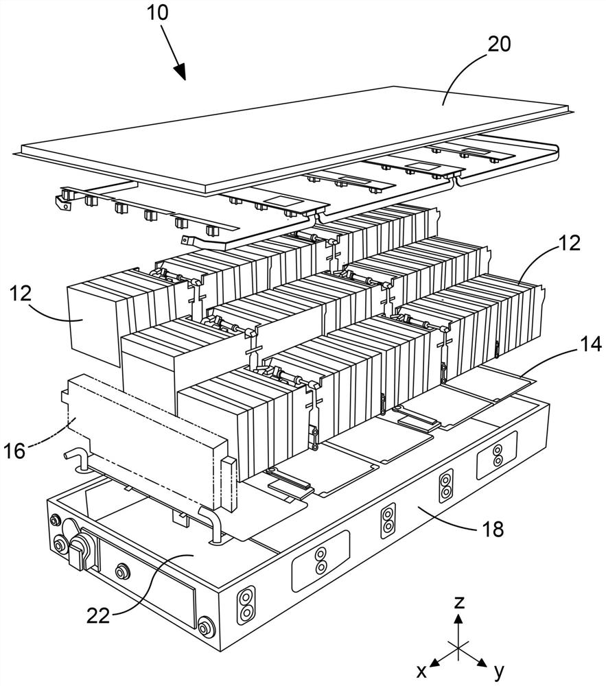
[0084] figure 1 An example of a battery pack is shown. figure 1 Our battery packs are designed for use with electric and hybrid vehicles, especially high horsepower applications such as buses, trucks, vans, construction equipment, etc.

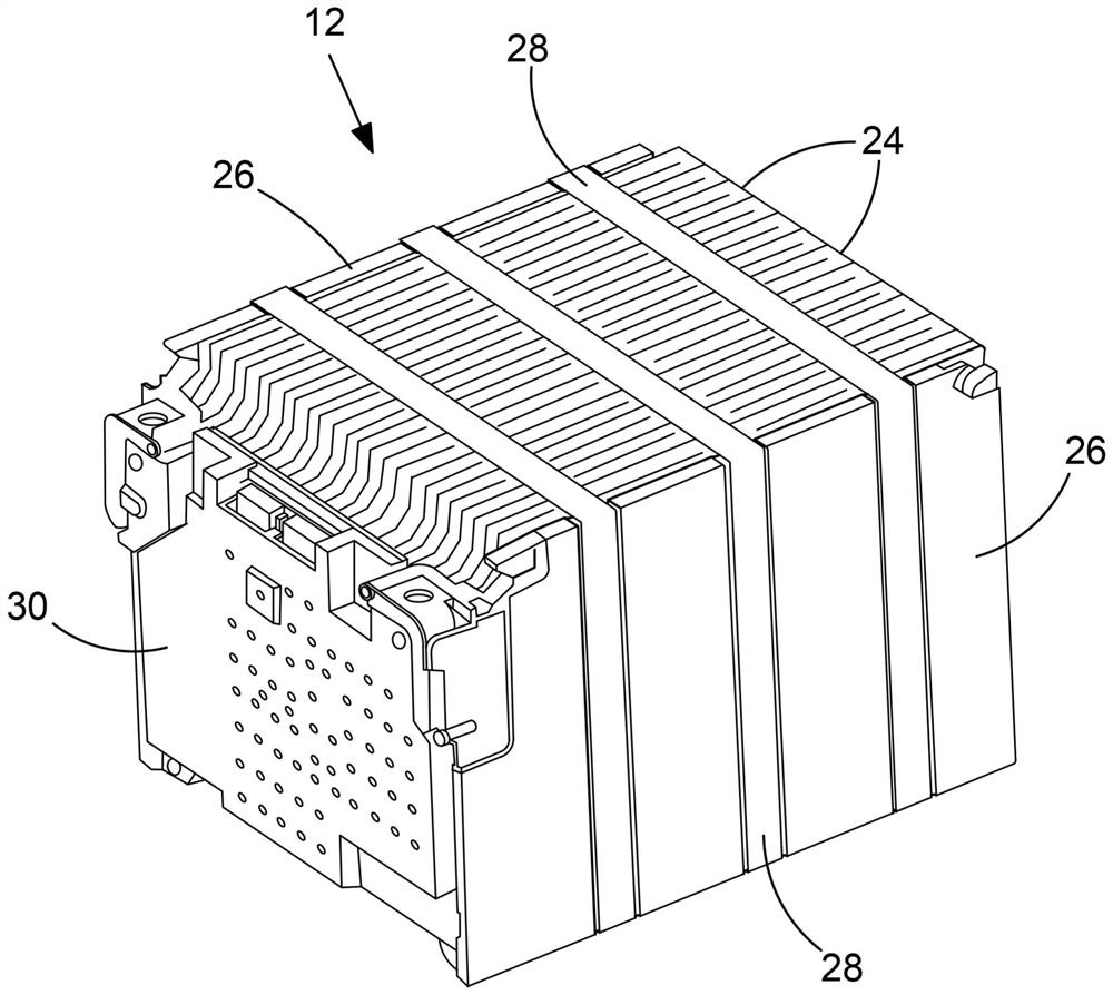
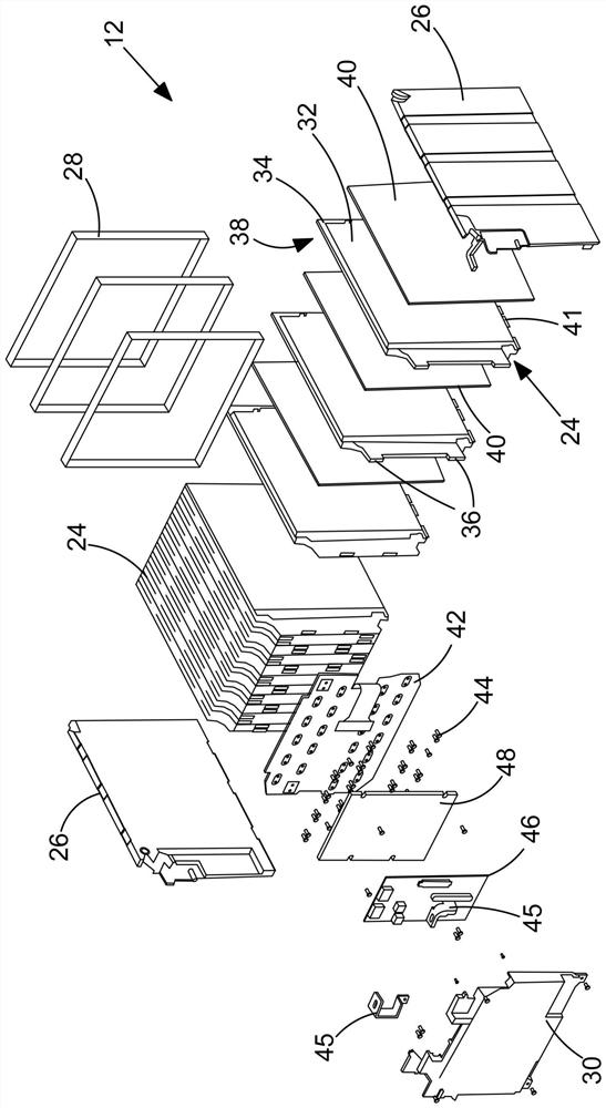
[0085] refer to figure 1 , the battery pack 10 includes: a plurality of battery modules 12 , a plurality of cooling plates 14 , a battery management system 16 , a surrounding frame 18 , a top plate 20 and a bottom plate 22 . In this example, fifteen battery modules 12 are provided in five rows of three modules. Each row of three battery modules 12 is located on a corresponding cooling plate 14 . The cooling plate 14 is hollow to allow coolant flow. A battery management system 16 is located at one end of the battery pack. In the assembled state, a top plate 20 and a bottom plate 22 are attached to the top and bottom of the frame 20, respectively. Battery modules 12 , cooling plate 14 , and battery management system 16 are housed within fr...


PUM


Abstract

The invention relates to detecting thermal events in battery packs. A battery module for use in a battery pack is disclosed. The battery module (12, 12 ') includes a plurality of battery cells (24, 25) and a sensing circuit (62) extending across the battery cells. A monitoring unit (46) is connected to the sensing circuit. The monitoring unit includes a continuity detector (66) configured to detect an interruption of continuity of the sensing circuit (62). This may allow a thermal event occurring in one of the plurality of cells to be detected.

Description

technical field [0001] The present invention relates to techniques for detecting uncontrolled thermal events in battery packs. The invention has particular, but not exclusive, application in traction applications such as electric or hybrid vehicles, in battery packs used in construction equipment, and the like, as well as stationary battery applications. Background technique [0002] Electric vehicles and hybrid vehicles such as cars, buses, vans and trucks use battery packs designed with high amp-hour capacity to provide power for sustained periods of time. A battery pack typically includes a large number of individual electrochemical cells connected in series and parallel to achieve overall energy, voltage and current requirements. To aid in manufacturing, assembly, and repair, the cells in a battery pack can be grouped into modules. These modules may include support structures and battery management units for managing charging and discharging of the cells. [0003] To ...

Claims


Application Information

Patent Timeline
IPC IPC(8): H01M10/42H01M10/48
CPCH01M10/425H01M10/486G01R31/3646G01R31/54G01R31/364G01R31/396H01M2010/4271H01M10/52H01M50/213H01M50/342Y02E60/10G01R31/3644G01R31/36H01M10/647G01R31/382H01M50/502H01M50/209H01M10/482H01M2200/106H02J7/0029
Inventor L·希里格斯D·里格尔斯M·D·纳尔逊T·A·拉什R·刘易斯
Owner CUMMINS INC
Why Eureka
Try Eureka