
Generator stator structure

A generator stator and stator wire technology, which is applied to the shape/pattern/structure of magnetic circuit, the shape/pattern/structure of winding conductor, electrical components, etc. The effect of increasing the area

Inactive Publication Date: 2009-10-07
JINZHOU HALLA ELECTRICAL EQUIP
View PDF0 Cites 3 Cited by
  • Summary
  • Abstract
  • Description
  • Claims
  • Application Information

AI Technical Summary

Problems solved by technology

[0003] The shape of the existing generator stator coil is as follows Figure 9 , Figure 10 , Figure 11 As shown, after the three-term coil is embedded on the iron core, the wires at the end of the stator winding are arranged relatively tightly and messily. When the generator is working, the stator winding generates a large amount of current. , the wind path generated by the rotation of the fan on the rotor will bypass the end of the stator winding and cool the end of the stator winding, which cannot dissipate the heat of the stator winding coil well

Method used


Image

  • Generator stator structure
  • Generator stator structure
  • Generator stator structure

Examples


Embodiment Construction

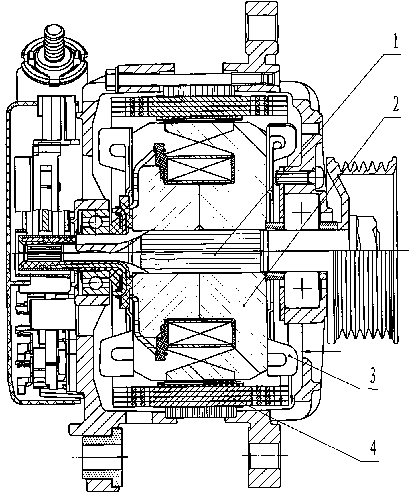
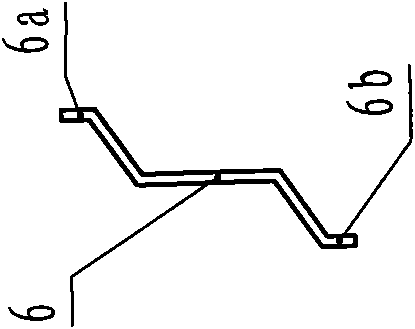
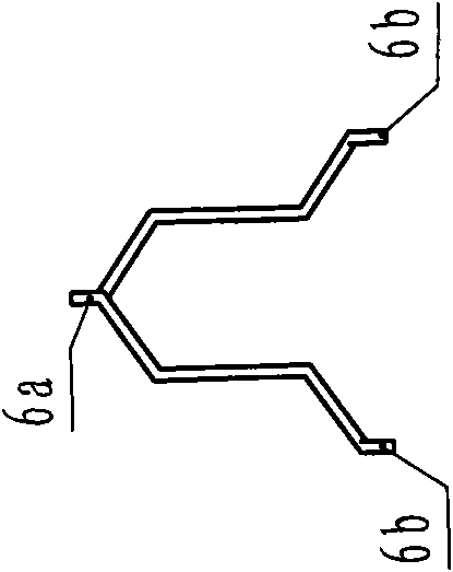
[0016] The following is a detailed description in conjunction with the drawings: As shown in the figure, the generator includes a main shaft 1, claw poles 2, fan 3, and a stator 4 connected to form a stator 4 includes an iron core 5, stator coil windings 6, lead wires 7, and positioning wedges 8. Composition; connect the stator wire connection end to form the stator coil winding 6 of tower-shaped symmetrical structure, each stator coil winding 6 is connected to the lead wire 7 at both ends respectively, and several stator coil windings 6 are installed in the positioning slot 5a of the iron core 5 , through positioning wedge 8 positioning.

[0017] Take the three-phase stator winding as an example

[0018] method one:

[0019] Make the stator wire 6 into figure 2 In the shape shown, one end 6a of the stator wire 6 and the other end 6b, each stator wire 6 is installed in the stator core 4, and the end 6a of one stator wire 6 is connected to the second stator wire 6. The end ...


PUM


Abstract

The invention relates to a generator stator structure which can improve current output; stator line connecting ends are connected to form the stator coil with a tower-shaped symmetrical structure, the two ends of each stator coil winding are respectively connected with outgoing lines for leading out, a plurality of the stator core windings are installed inside an iron core slot and positioned by a positioning wedge. The structure has the advantages that: a plurality of air gaps are left at the two ends of the stator iron core and the end part of the stator winding, thus increasing the area of the wind path. Wind generated by the rotation of a fan can pass through the air gaps, and due to the existence of the air gaps, more wind can pass the surface of the end part of the stator winding and bring away more heat, thus reinforcing the heat dissipation property of the end part of the stator winding. The temperature of the stator winding can be reduced by about 10 DEG C under the condition of the same output power, and the output current can be improved by 5 amperes under the condition of the same stator winding temperature.

Description

technical field [0001] This patent relates to a generator stator structure, which is suitable for various alternators. technical background [0002] When the generator is working, the shaft rotates and drives the fan to rotate. The wind generated by the rotation of the fan enters from the front of the generator, and blows to the end 5a of the stator winding 5 through the fan 3 . [0003] The shape of the existing generator stator coil is as follows Figure 9 , Figure 10 , Figure 11 As shown, after the three-term coil is embedded on the iron core, the wires at the end of the stator winding are arranged relatively tightly and messily. When the generator is working, the stator winding generates a large amount of current. , the wind path generated by the rotation of the fan on the rotor will bypass the end of the stator winding and cool the end of the stator winding, which cannot effectively dissipate heat from the coil of the stator winding. Contents of the invention ...

Claims


Application Information

Patent Timeline
Patent Type & Authority Applications(China)
IPC IPC(8): H02K1/16H02K3/487H02K3/28
Inventor 陈蕴超韩立臣牟晓松孙玲郝立国
Owner JINZHOU HALLA ELECTRICAL EQUIP
Learn More