
Dynamic wave wet dust collection technology of non-ferrous metallurgical furnace

A technology of dynamic wave and metallurgical furnace, which is applied to the separation of dispersed particles, chemical instruments and methods, combined devices, etc., can solve the problems of dust collection pipeline blockage, loss of precious metals, low-altitude pollution, etc., and achieve improved dust collection efficiency and improved recycling. horizontal effect

Active Publication Date: 2013-10-09
YUNNAN COPPER CO LTD
View PDF0 Cites 0 Cited by
  • Summary
  • Abstract
  • Description
  • Claims
  • Application Information

AI Technical Summary

Problems solved by technology

[0002] At present, most of the dust collection systems involved in the pyrometallurgy of precious metal production are completed by the pulse bag dust collection system. The dew point of the gas is low, so that the flue gas is easy to condense in the pipeline and the bag filter, which will block the system and form low-altitude flue gas pollution.
Our unit uses non-ferrous metallurgical furnaces to smelt copper electrolytic anode slime. The raw materials contain high Se and moisture. When condensation occurs, it is easier to bond pipes and cloth bags, resulting in increased resistance of the entire system, reduced suction, and frequent blockage of dust collection pipes. It is difficult to dredge the agglomeration of the flue gas after absorbing moisture, which causes a large amount of flue gas escaping from the furnace mouth, causing serious low-altitude pollution, which has a great impact on the environment and employees, and causes a large loss of precious metals
In addition, due to the unsatisfactory dust collection effect of the later system, frequent replacement of the bag and its auxiliary equipment is required. In addition to affecting normal production, the maintenance cost of the system is also rising

Method used


Image

  • Dynamic wave wet dust collection technology of non-ferrous metallurgical furnace
  • Dynamic wave wet dust collection technology of non-ferrous metallurgical furnace

Examples


Embodiment Construction

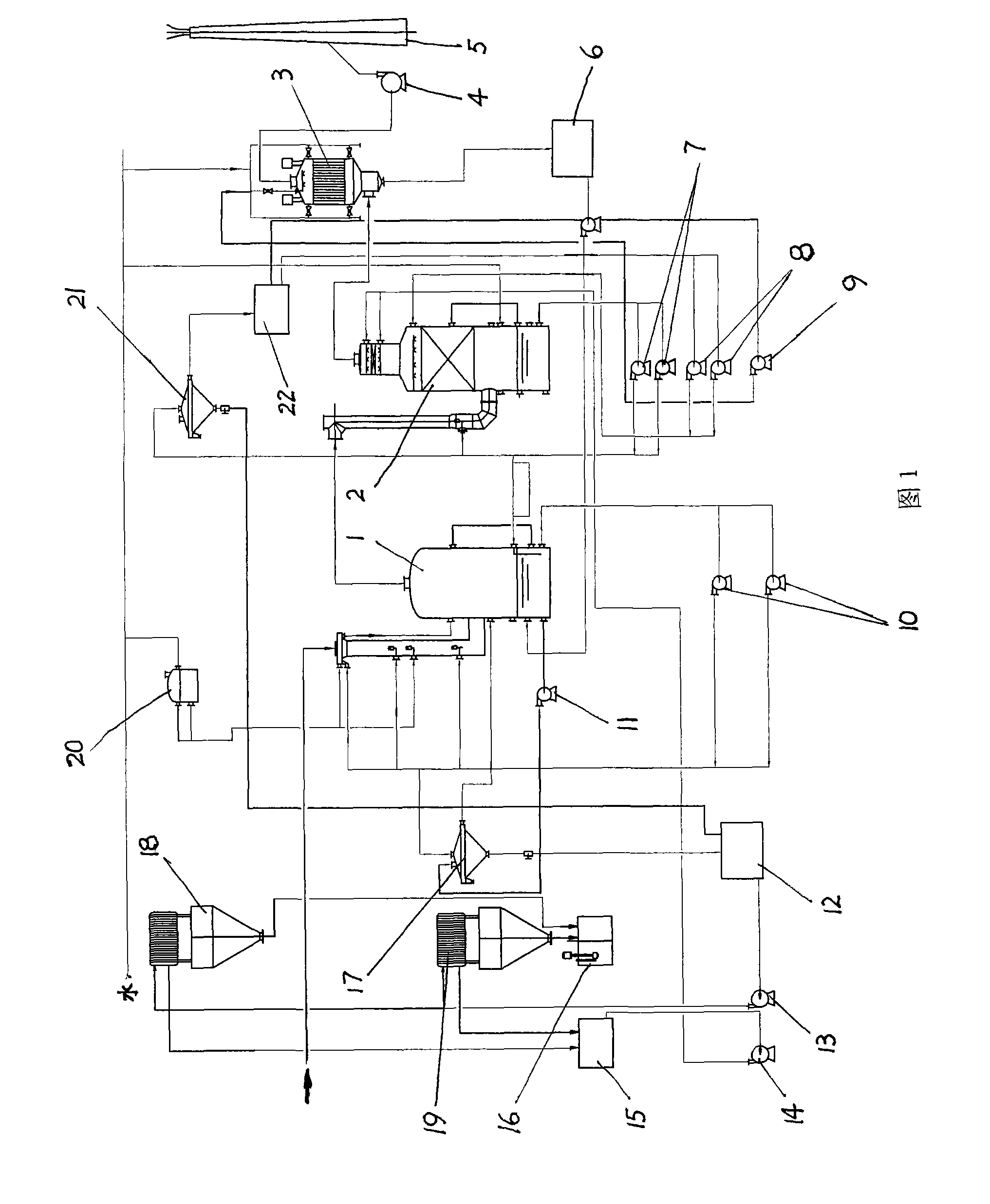
[0007] According to the process proposed by the present invention, a set of process flow of non-ferrous metallurgical furnace power wave wet dust collection technology has been established in the rare and expensive branch of the applicant. The main equipment in this project example is as follows: a first-level power wave tower with a specification of Φ650 / Φ550 / Φ2000×11400mm, a second-level power wave tower with a specification of Φ600 / Φ2700×11000mm, an electric demister, and a high-pressure centrifugal fan , two box-type plate and frame filter presses, one No. 1 dense tank of 2500×2500mm, one No. 2 dense tank of 4000×4000mm, one large and small clear liquid tank and several circulation pumps.

[0008] The high-temperature flue gas discharged from the non-ferrous metallurgical furnace for treatment, the dust content in the flue dust is 5000-8000Nm 3 / h, through the 200KW centrifugal fan 4 to induce air, after coarse dust collection and cooling in the gravity settling chamber, i...


PUM


Abstract

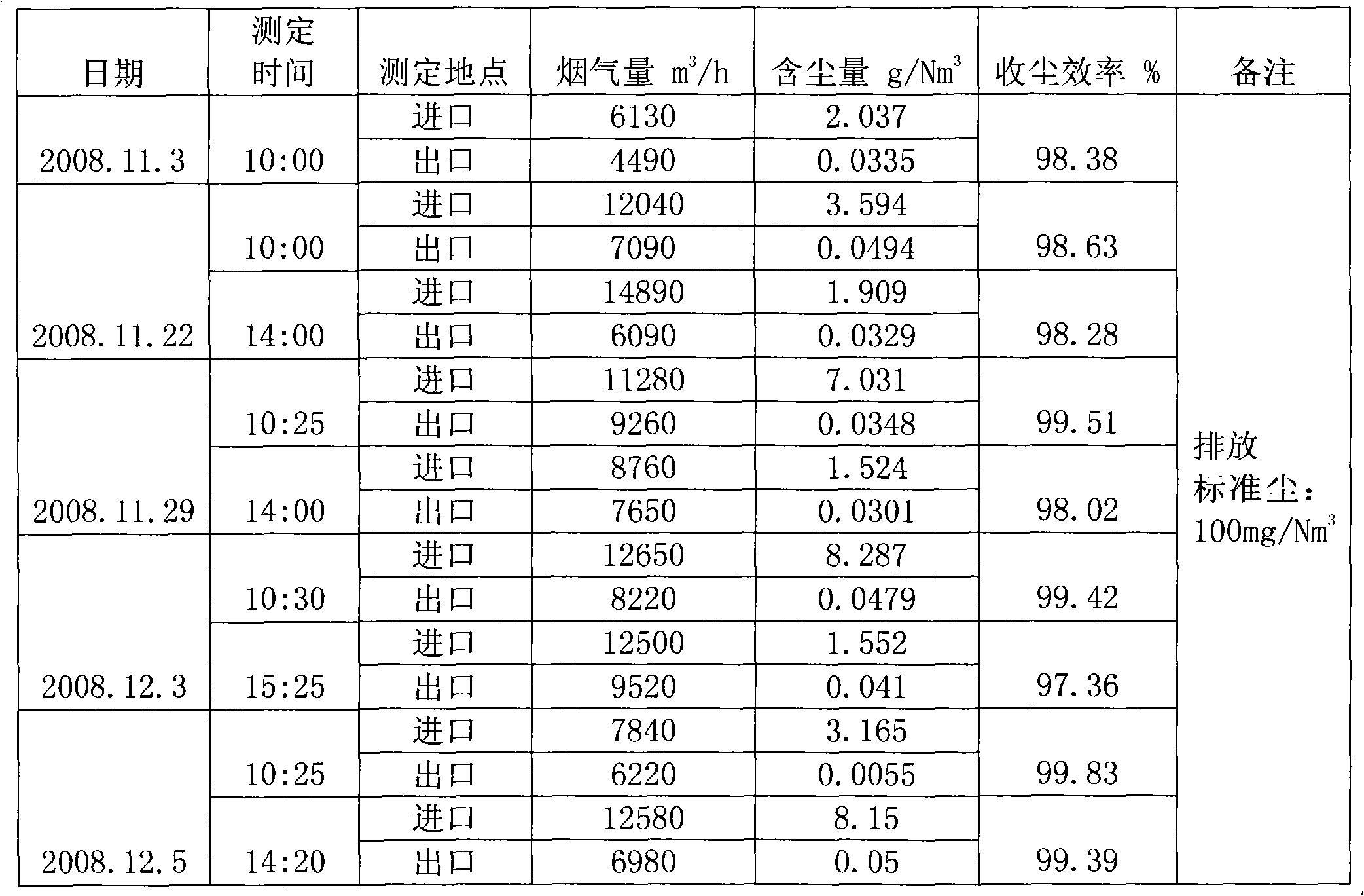
The invention relates to a dynamic wave wet dust collection technology of a non-ferrous metallurgical furnace, which adopts a dynamic wave tower and a wet electrostatic mist eliminator for dust collection process. The technology is characterized in that a three-stage wet dust collection system is used for processing high-temperature flue gas discharged from a non-ferrous metallurgical furnace; the first stage adopts a primary dynamic wave tower for removing over 4 micrometer liquid drop containing dust; the second stage adopts a secondary dynamic wave tower for removing 3 to 4 micrometer liquid drop containing dust; and the third stage adopts a wet electrostatic mist eliminator for removing below 3 micrometer liquid drop containing dust. The technology has the advantages that the dust collection efficiency is greatly improved, the content of dust in discharged tail gas totally meet new national standards by further processing the filter liquor and flue dust, the recycle level of valuable elements of Ag and Se is improved, and the damage of noxious gas to environment and workers is reduced to the minimum.

Description

1. Technical field [0001] The invention relates to the field of environmental protection in the nonferrous smelting industry, in particular to a nonferrous metallurgical furnace dynamic wave wet dust collection process. 2. Technical background [0002] At present, most of the dust collection systems involved in the pyrometallurgy of precious metal production are completed by the pulse bag dust collection system. The dew point of the gas makes the flue gas easy to condense in the pipeline and the bag filter, which will block the system and form low-altitude flue gas pollution. Our unit uses non-ferrous metallurgical furnaces to smelt copper electrolytic anode slime. The raw materials contain high Se and moisture. When condensation occurs, it is easier to bond pipes and cloth bags, resulting in increased resistance of the entire system, reduced suction, and frequent blockage of dust collection pipes. It is difficult to dredge the agglomeration of flue gas after absorbing mois...

Claims


Application Information

Patent Timeline
Patent Type & Authority Patents(China)
IPC IPC(8): B01D50/00
Inventor 徐养良汤家道攸骏刘文权杨晓明刘利民刘伟明杨勇王钲代峰献代红坤张邦琪史谊峰徐翔
Owner YUNNAN COPPER CO LTD
Learn More