Improved natural gas drive oil production method

A technology for natural gas and natural gas injection, which is applied in the field of oil recovery and development effect of oil recovery and natural gas injection to produce crude oil, can solve the problems of lower displacement efficiency, less crude oil, natural gas channeling, etc. economic effect

Active Publication Date: 2009-10-14
PETROCHINA CO LTD
View PDF2 Cites 7 Cited by
  • Summary
  • Abstract
  • Description
  • Claims
  • Application Information

AI Technical Summary

Benefits of technology

This technology improves the efficiency of producing heavy oils while reducing wastage or pollution associated therewith during traditional methods such as water-based drilling (WBF) or steam exploration techniques that use geothermal energy sources like hot brine). By continuously reconnecting these areas throughout the process, it becomes possible to produce more efficiently without causing environmental concerns due to excessive emissions.

Problems solved by technology

This patented technical problem addressed by this patents relates to improving the efficient usage of naturally-produced gases during oil extraction processes such as drilling or hydraulic fracturing operations while also reducing their impact on other areas within an underground environment like aquifers due to these channels created when they are introduced with them.

Method used


Image

  • Improved natural gas drive oil production method
  • Improved natural gas drive oil production method
  • Improved natural gas drive oil production method

Examples


Embodiment 1

[0034] Embodiment 1: Taking a block with an oil reservoir pressure of 12 MPa as an example to carry out an improved natural gas flooding recovery process, the detailed description will be given.

[0035] In a block of an oilfield, the depth of the oil layer is 1800 meters, and the thickness of the oil layer is 10 meters, and the depletion production has been carried out. Reservoir pressure is 12 MPa after depleted production. A decision was made to develop improved natural gas flooding.

[0036] refer to Figure 4 . Step 1: Well pattern in the natural gas flooding area: a nine-point well pattern is adopted, the gas injection well 1 is in the middle, and there are 8 production wells 2 around it, and the 8 production wells 2 are arranged in a rectangle. The gas injection well 1 is 100-200 meters away from the near production well 2, and 140-280 meters away from the far production well 2. In the present embodiment, there are 150 meters away from the nearer production well 2, ...

Embodiment 2

[0042] Embodiment 2: Taking a block with an oil reservoir pressure of 25 MPa as an example to carry out an improved natural gas flooding recovery process, the detailed description will be given.

[0043] In a block of an oilfield, the depth of the oil layer is 3000 meters, and the thickness of the oil layer is 18 meters, and the depletion production has been carried out. Reservoir pressure is 25 MPa after depleted production. A decision was made to develop improved natural gas flooding.

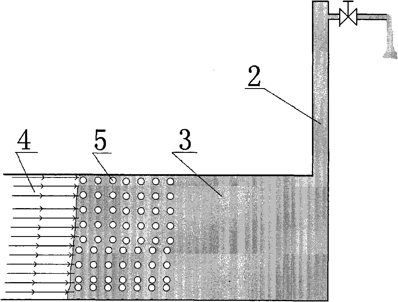
[0044] refer to image 3 . Step 1: Improve the well pattern in the natural gas flooding area, adopt a nine-point well pattern, the gas injection well is in the middle, and there are 8 production wells around it. The distance between the production well 2 and the gas injection well 1 is 150 meters, and the distance between the production well 2 and the gas injection well 1 is 200 meters. . Gas injection equipment is connected to gas injection wells, and oil production equipment is connecte...


PUM


Abstract

The invention relates to an improved natural gas drive oil production method which is applied to oil production in oil fields. The invention is characterized in that A. natural gas is injected into a gas injection well; B. under the condition of continuous injection of natural gas, peripheral production wells are opened for production and closed for stopping production discontinuously. In the period of closing the well, the pressure of an oil pool at the periphery of the gas injection well raises, and when the pressure raises to a certain extent, the production wells are opened for production; with the production of the opened production wells, the pressure of the oil pool at the periphery of the gas injection well decreases and when the pressure decreases to a certain extent, the production wells are closed for stopping production; and the above steps are repeatedly circulated. The method has the effects that the drive oil effect can be improved and when the pressure raises, part of natural gas can be dissolved into the crude oil; when the pressure decreases, the natural gas can be separated from the crude oil so as to form a plurality of small bubbles and the volume of the crude oil is obviously expanded compared with the volume of the crude oil when the natural gas is not separated. As the natural gas is injected continuously, the expanded crude oil expands to downstream, thus driving the downstream crude oil to flow to the downstream production wells.

Description


Claims


Application Information

Patent Timeline
Owner PETROCHINA CO LTD
Why Eureka
Try Eureka