Planarizing sheet and process for preparation of color filter using the same

A flattening and color filter technology, used in applications, instruments, filters, etc., can solve the problems of poor mold release processing on the outer peripheral surface, excessively hard metal rollers, and reduced contrast, and achieve the effect of improving surface smoothness

Inactive Publication Date: 2009-10-14
SUMITOMO RUBBER IND LTD
View PDF2 Cites 3 Cited by
  • Summary
  • Abstract
  • Description
  • Claims
  • Application Information

AI Technical Summary

Problems solved by technology

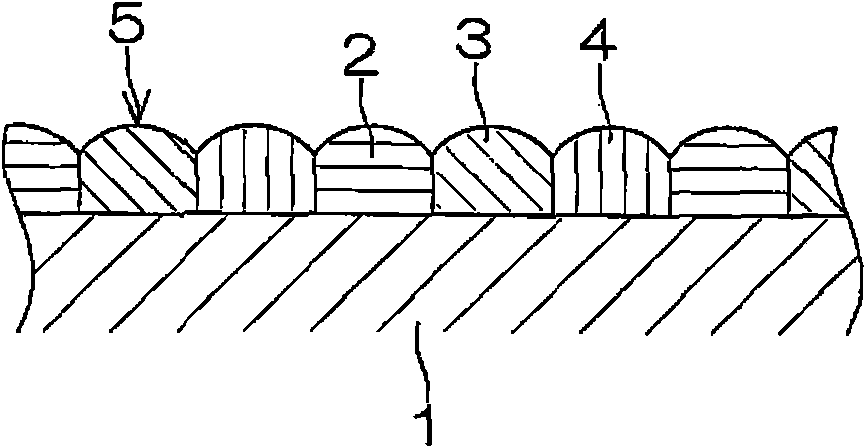
[0003] However, the stripe patterns of each color formed by printing the transparent ink colored in the above-mentioned colors by various printing methods have a surface that is low at both ends of the stripe and high at the center due to the surface tension of the transparent ink. Therefore, the surface of the transparent resin layer, which is a collection of stripe patterns of each color, forms a concavo-convex shape corresponding to the protruding shape of the above-mentioned stripe pattern, and there is a problem that the contrast of the display is lowered due to the diffuse reflection of light caused by the above-mentioned concavities and convexities. , or such as in the case of an LCD when uneven response of the liquid crystal occurs
[0011] However, in the case of using the same roll wound with an offset blanket as that used when printing a stripe pattern by the lithographic offset printing method described in H02-297502A (1990), it is considered that the offset blanket may be The transparent ink from the plate is well received and transferred to the surface of the substrate well, and the wettability of the surface to the transparent ink and the softness as a whole are set, so there is the following problem: The transparent ink of the transparent resin layer is reverse-printed on the surface of the offset printing tape, causing defects such as recesses on the transparent resin layer, or the transparent resin layer is easily damaged, and it is difficult to uniformly flatten the entire transparent resin layer
[0012] In addition, when using metal rolls or the like after the outer peripheral surface has been released from the mold described in H08-075914A (1996) and H08-234013A (1996), the above-mentioned metal rolls are too hard and cannot be flexibly adapted to the thickness of the transparent resin layer. deviation, etc., so there is still a problem that the entire transparent resin layer is difficult to be flattened uniformly
In addition, there is also a problem that the release process of the outer peripheral surface of the above-mentioned metal roller or the like is deteriorated, and when the transparent ink forming the transparent resin layer becomes easily reverse-printed on the above-mentioned outer peripheral surface, the whole must be replaced.
[0014] However, it has also been clarified that as the above-mentioned planarizing sheet, it has the same structure as a conventional offset printing blanket, and only slightly adjusted the characteristics such as the wettability of the contact surface to the transparent ink and the flexibility as a whole. In the case of the flattening sheet, especially when the flattening sheet is wound and fixed on the outer peripheral surface of the roll, when foreign matter or the like is sandwiched between the two, the shape of the foreign matter is clearly present as a protrusion in the contact of the flattening sheet. On the flattened transparent resin layer, defects such as recesses corresponding to the above-mentioned protrusions are likely to occur.

Method used


Image

  • Planarizing sheet and process for preparation of color filter using the same
  • Planarizing sheet and process for preparation of color filter using the same
  • Planarizing sheet and process for preparation of color filter using the same

Examples


Embodiment 1

[0060] As the substrate layer, a PET film [T60 manufactured by Toray Co., Ltd.] having a thickness of 100 μm, having an arithmetic mean roughness Ra of 11.5 nm of roughness curves on both sides, a tensile modulus (23° C.) of 210 MPa, and a thickness of 100 μm was prepared. Then, cut the above-mentioned PET film into a rectangular shape of 300 mm in length and 400 mm in width, and stick mending tape on the edges of the two long sides of the rectangle on one side, and fix it with the above-mentioned one side of the PET film facing upwards. In the state on the flat disk, the above-mentioned sewing tape was used as a thickness guide (guide), and a coating rod made of stainless steel with a diameter of 12 mm and whose outer peripheral surface was ground and finished was applied to the above-mentioned single side by the bar coating method. After coating the silicone resin-based coating liquid [SEPA-COAT, a registered trademark manufactured by Shin-Etsu Chemical Co., Ltd., the surface...

Embodiment 2

[0063] In addition to using the registered trademark SEPA-COAT manufactured by Shin-Etsu Chemical Co., Ltd. and KS-830 manufactured by the same company in a weight ratio of 40:60 [surface tension of a single cured product (23°C): 38mN / m] as a mold release A flattened sheet of Example 2 was produced in the same manner as in Example 1 except for the silicone resin-based coating liquid used as a raw material for the layer. The surface tension (23° C.) of the surface of the release layer was 28 mN / m, the arithmetic mean roughness Ra of the roughness curve was 8.7 nm, and the thickness was 1 μm.

Embodiment 3

[0069] In addition to using the registered trademark SEPA-COAT manufactured by Shin-Etsu Chemical Co., Ltd. and KS-837 manufactured by the same company in a weight ratio of 80:20 [surface tension of a single cured product (23°C): 16mN / m] as a mold release A flattened sheet of Example 3 was produced in the same manner as in Example 1 except for the silicone resin-based coating liquid as the raw material of the layer. The surface tension (23° C.) of the surface of the release layer was 16 mN / m, the arithmetic mean roughness Ra of the roughness curve was 18 nm, and the thickness was 1 μm.


PUM

PropertyMeasurementUnit
surface tensionaaaaaaaaaa
surface roughnessaaaaaaaaaa

Abstract

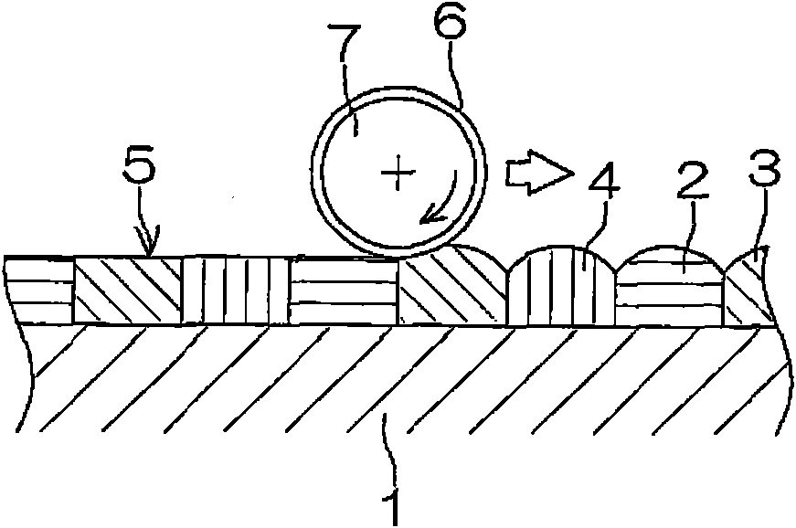
The present inventoin provides a flattening sheet successively laminated releasing layer, substrate layer and elastic layer, the releasing layer has ain a roughness curve, a base material layer which is a surface of the releasing layer side and has ain a roughness curve and an elastic layer having 0.5-20 MPa elastic modulus (23[deg.]C) and 0.1-5 mm thickness. The flattening sheet is capable of uniformly flattening the whole transparent resin layer, preventing transparent ink forming the transparent resin layer from reversely being transferred and hardly causing defect on the transparent resin layer due to the incorporation of foreign matter and a method of manufacturing a color filter using the flatening sheet. The method of manufacturing is carried out by rolling a roller 7 on which the flattening sheet 6 is wound and fixed so that the releasing layer exists outside to be in contact with the surface of the transparent resin layer 5 formed on a substrate 1 to flatten the surface.

Description

technical field [0001] The present invention relates to a flattening sheet for converting the above-mentioned transparent resin layer by bringing it into contact with the surface of at least partly colored transparent resin layer constituting the color filter, and a method of manufacturing a color filter using the above-mentioned flattening sheet. The surface of the resin layer is flattened. Background technique [0002] A color filter used in a flat panel display such as a liquid crystal display (LCD) is manufactured by regularly arranging and printing a stripe pattern corresponding to each pixel on a transparent substrate to form a transparent resin layer. The coloring is formed by corresponding to the transparent inks of the respective colors of red (R), green (G), and blue (B) pixels constituting the above-mentioned liquid crystal display or the like. [0003] However, the stripe patterns of each color formed by printing the transparent ink colored in the above-mentione...

Claims


Application Information

Patent Timeline
Patent Type & Authority Applications(China)
IPC IPC(8): G02B5/20
CPCB29C53/16B29D11/00634G02B5/201G02F1/133516
Inventor 越智淳杉谷信近藤康彦
Owner SUMITOMO RUBBER IND LTD
Why Eureka
Try Eureka