Relay control circuit of hybrid vehicle
A relay control and main relay technology, applied in relays, circuits, electrical components, etc., can solve the problems of secondary injury to drivers and passengers, contact sintering, and imperfect hybrid vehicles, so as to reduce potential safety hazards and prevent secondary damage. damage effect
- Summary
- Abstract
- Description
- Claims
- Application Information
AI Technical Summary
Problems solved by technology
Method used
Image

Examples
Embodiment 1
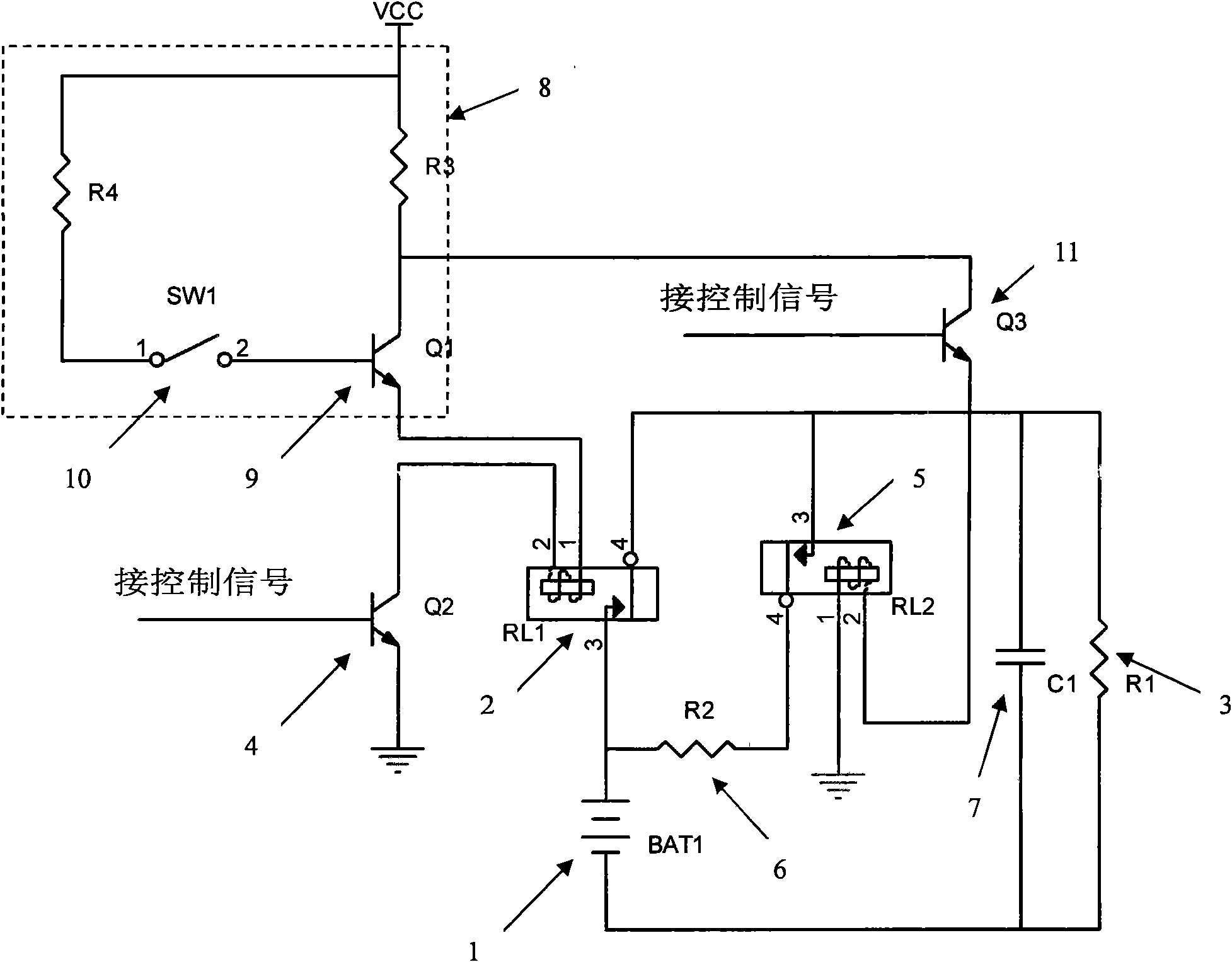
[0021] Such as figure 1 As shown, the relay control circuit of this embodiment includes a power supply 1, an output terminal of the main relay 2, and a load 3 connected in series in sequence. The input terminal of the main relay 2 is connected with a switch 4 that can control the pull-in of the main relay 2. The output end is connected in parallel with a pre-charging circuit, and the pre-charging circuit is formed by connecting a pre-charging relay 5 and a current-limiting resistor 6 in series. A charging capacitor 7 is connected in series at the output end of the relay 2, and the charging capacitor 7 is connected in parallel with the load 3; the input end of the main relay 2 is also connected with a protection circuit 8 which can control the disconnection of the main relay 2 when the car collides.
[0022] The protection circuit 8 is composed of a switch 9 connected in series to the input end circuit of the main relay 2 and an impact sensor 10 that can control the switch 9 to...
Embodiment 2
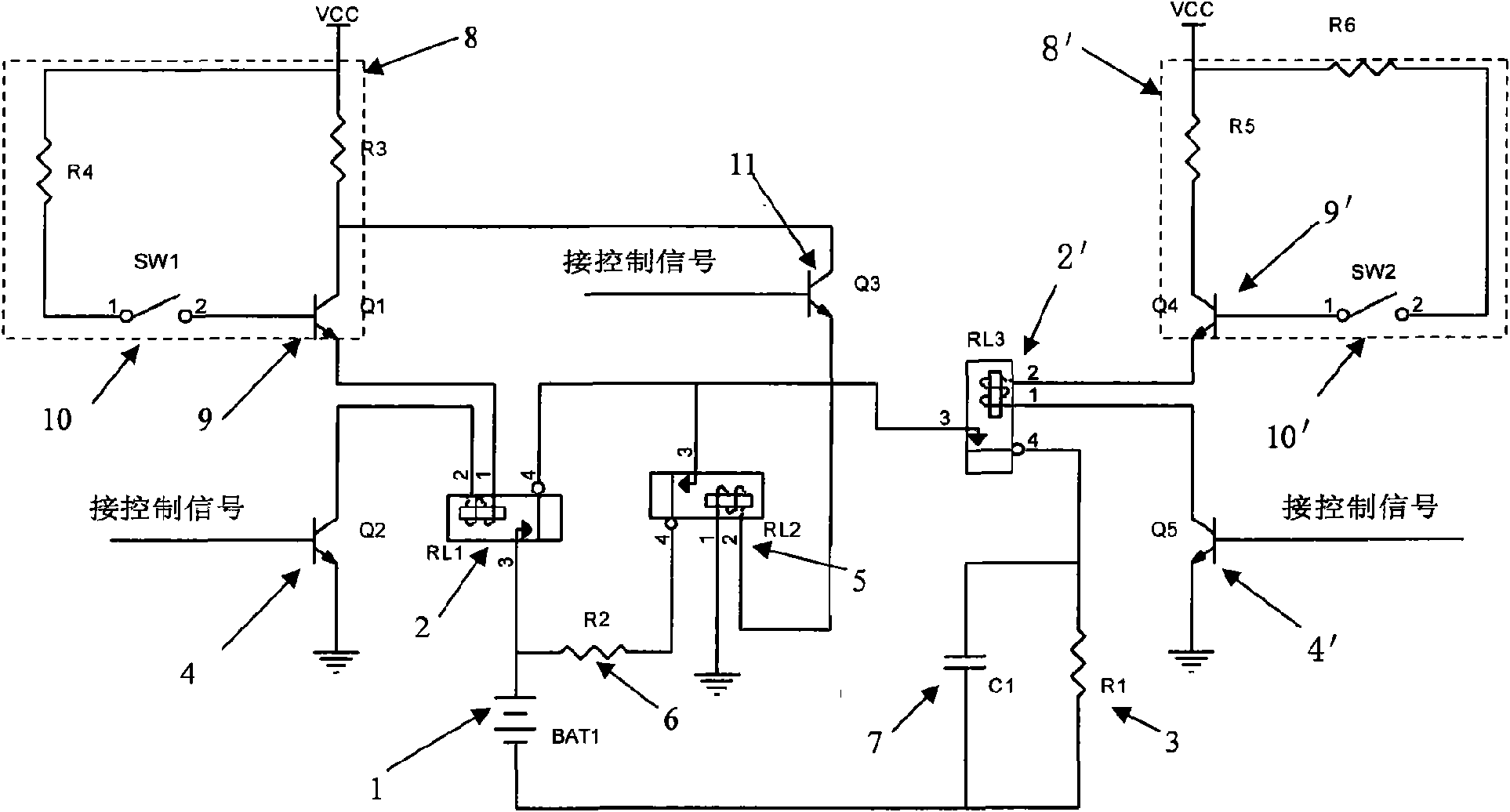
[0028] Different from Embodiment 1, the relay control circuit of this embodiment also includes a secondary relay 2', the output terminal of the secondary relay 2' is connected in series with the output terminal of the main relay 2 and the parallel circuit composed of the pre-charging circuit and Between the loads 3, the input end of the auxiliary relay 2' is connected with a switch 4' which can control the auxiliary relay 2' to be turned on and a protection circuit 8' which can control the auxiliary relay 2' to be disconnected when the vehicle collides.
[0029] The protection circuit 8' is composed of a switch 9' connected in series to the input end circuit of the main relay 2' and an impact sensor 10' which can control the switch 9' to be disconnected when the vehicle collides.
Embodiment 3
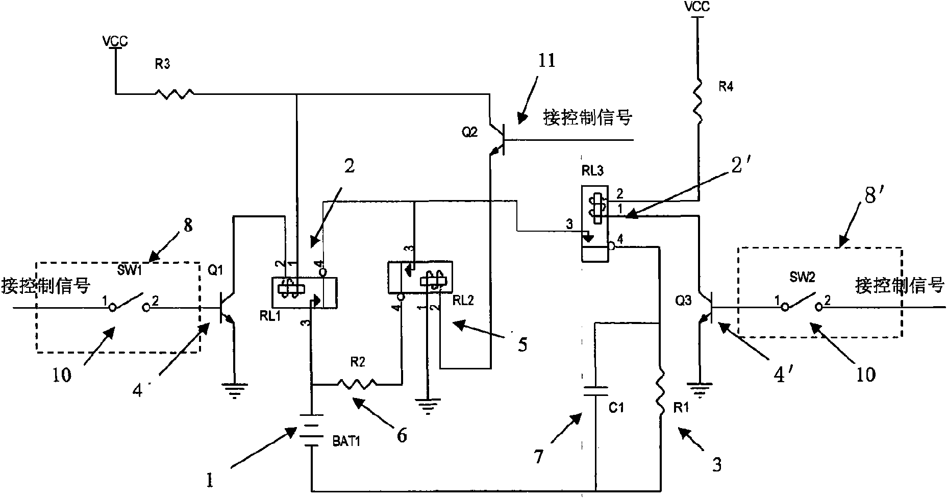
[0031] Different from Embodiment 2, the protection circuit 8 in the relay control circuit of the present embodiment is a collision sensor 10 that is connected with the switch 4 and can control the switch 4 to be disconnected when the automobile collides; the protection circuit 8' is a The switch 4' is connected to the collision sensor 10' which can control the switch 4' to be disconnected when the car collides. The collision sensor 10, 10' is equivalent to a normally closed switch, which will only be disconnected when the automobile collides.
[0032] Compared with Embodiment 2, this embodiment can effectively save costs.
PUM
 Abstract
Description
Claims
Application Information
 - Generate Ideas
- Intellectual Property
- Life Sciences
- Materials
- Tech Scout
- Unparalleled Data Quality
- Higher Quality Content
- 60% Fewer Hallucinations
Browse by: Latest US Patents, China's latest patents, Technical Efficacy Thesaurus, Application Domain, Technology Topic, Popular Technical Reports.
© 2025 PatSnap. All rights reserved.Legal|Privacy policy|Modern Slavery Act Transparency Statement|Sitemap|About US| Contact US: help@patsnap.com