
Connector of automatic charging device used for robot

An automatic charging device and robot technology, applied in the direction of coupling device, two-part connecting device, secondary battery charging/discharging, etc., can solve the problems of immature design of automatic charging system, large docking error, poor error correction performance, etc., to achieve The effect of simple structure, small cumulative error and large contact surface

Inactive Publication Date: 2011-03-30
SHANGHAI UNIV
View PDF0 Cites 0 Cited by
  • Summary
  • Abstract
  • Description
  • Claims
  • Application Information

AI Technical Summary

Problems solved by technology

Although the research on the automatic charging system of mobile robots began as early as 1948, the current design of automatic charging systems for mobile robots is still immature.
The connectors of the automatic charging system are all specially designed independently, and have the following disadvantages: poor versatility, poor error correction performance, large docking error, large cumulative error, and a series of shortcomings such as small adaptability

Method used


Image

  • Connector of automatic charging device used for robot
  • Connector of automatic charging device used for robot
  • Connector of automatic charging device used for robot

Examples


Embodiment Construction

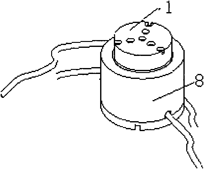
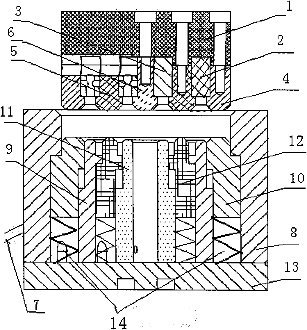
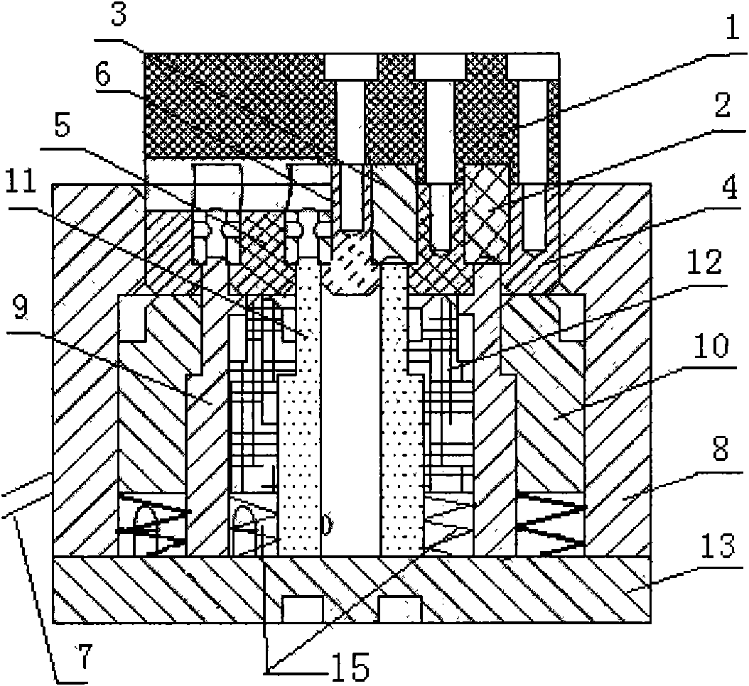
[0014] The plug socket base 1 is a round platform structure made of insulating material, mainly the cage of the plug socket, which is connected to the miniature cover 6 through a bolt located in the center of the base 1, and through 3 evenly distributed outer rings. The bolts are connected with the large ring-shaped cover 4, and connected with the small ring-shaped cover 5 by 3 evenly distributed bolts on the secondary outer ring, so that an annular groove is formed between the base 1, the large ring-shaped cover 2 and the small ring-shaped cover 5, and the base 1, A small annular groove is formed between the small ring-shaped cover 5 and the miniature cover 6; the large ring-shaped cover 2, the small ring-shaped cover 5 and the miniature cover 6 are all made of an insulating material in a circular structure, and one end is designed as a stepped structure, that is, there are The convex shoulder is used to fix the positions of the large annular contact and the small annular cont...


PUM


Abstract

The invention relates to a connector of an automatic charging device used for a robot, comprising a plugging female head and a plugging male head. The plugging female head has a round platform structure, is provided with a large annular groove and a small annular groove which have same center of a circle, are respectively and internally provided with a large annular contact and a small annular contact and are respectively and externally connected with a power supply by a live line and a zero line. The plugging male head also has a round platform structure, is provided with a large annular contact column and a small annular contact column which are inserted and matched with the large annular groove and the small annular groove of the plugging female head, thus respectively contacting with the large annular contact column point and the small annular contact point and being connected to a power supply device of the robot by wires; and the large annular contact column and the small annularcontact column are respectively arranged in a large elastic sleeve ring and a small elastic sleeve ring. The connector of the automatic charging device has large contact surface of energization and has safe and reliable energization; the contacts of the female head and the contact columns of the male head are respectively embedded in the annular grooves, thus being capable of preventing electricshock accidents. The connector of the automatic charging device has simple structure, strong commonality and large application range.

Description

technical field [0001] The patent of the present invention relates to a connector of an automatic charging device for a robot. Background technique [0002] The design of the automatic charging system of the mobile robot is a key link in the intelligentization of the robot. The automatic charging system consists of two main parts: the connector (to realize the connection between the internal power supply of the robot and the external power supply), and the auxiliary plug-in device (to assist the robot to realize the connection between the power supply device to be charged and the unconnected power supply). Although the research on the automatic charging system for mobile robots began as early as 1948, the current design of the automatic charging system for mobile robots is still immature. The connectors of the automatic charging system are specially designed independently, and have the following disadvantages: poor versatility, poor error correction performance, large docki...

Claims


Application Information

Patent Timeline
Patent Type & Authority Patents(China)
IPC IPC(8): H01M10/44B25J19/00H01R24/00
CPCY02E60/12Y02E60/10
Inventor 何永义赵伟张海洪李治斌
Owner SHANGHAI UNIV
Learn More