


Quick Research
Generate reliable direction feasibility study reports for your R&D in just a few steps.

Technical Q&A
Discover and master advanced knowledge NOW. Basics, ideas, possibilities, all at once.

Find Solutions
As an expert in R&D theories, this can generate solutions to your technical problems instantly.

Evaluate Feasibility
Analyze your overall solution with one click, know your potential R&D risks in advance.

Monitor Landscape
Get weekly tech updates, stay abreast of the latest tech innovations and key insights.
Homokinetic joint
A constant velocity universal joint, universal joint technology, applied in elastic couplings, mechanical equipment, couplings, etc., can solve problems such as hindering the good operation of universal joints
- Summary
- Abstract
- Description
- Claims
- Application Information
AI Technical Summary
Problems solved by technology
Method used
Image

Examples
Embodiment Construction
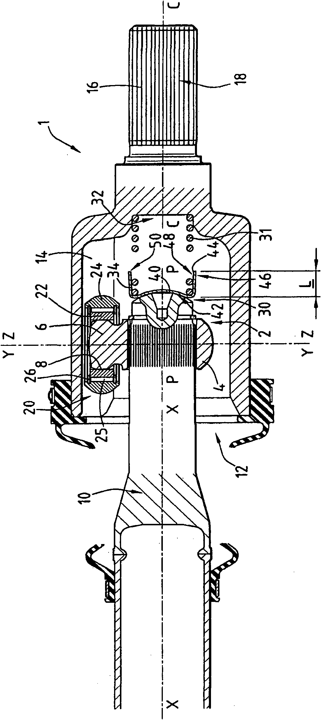
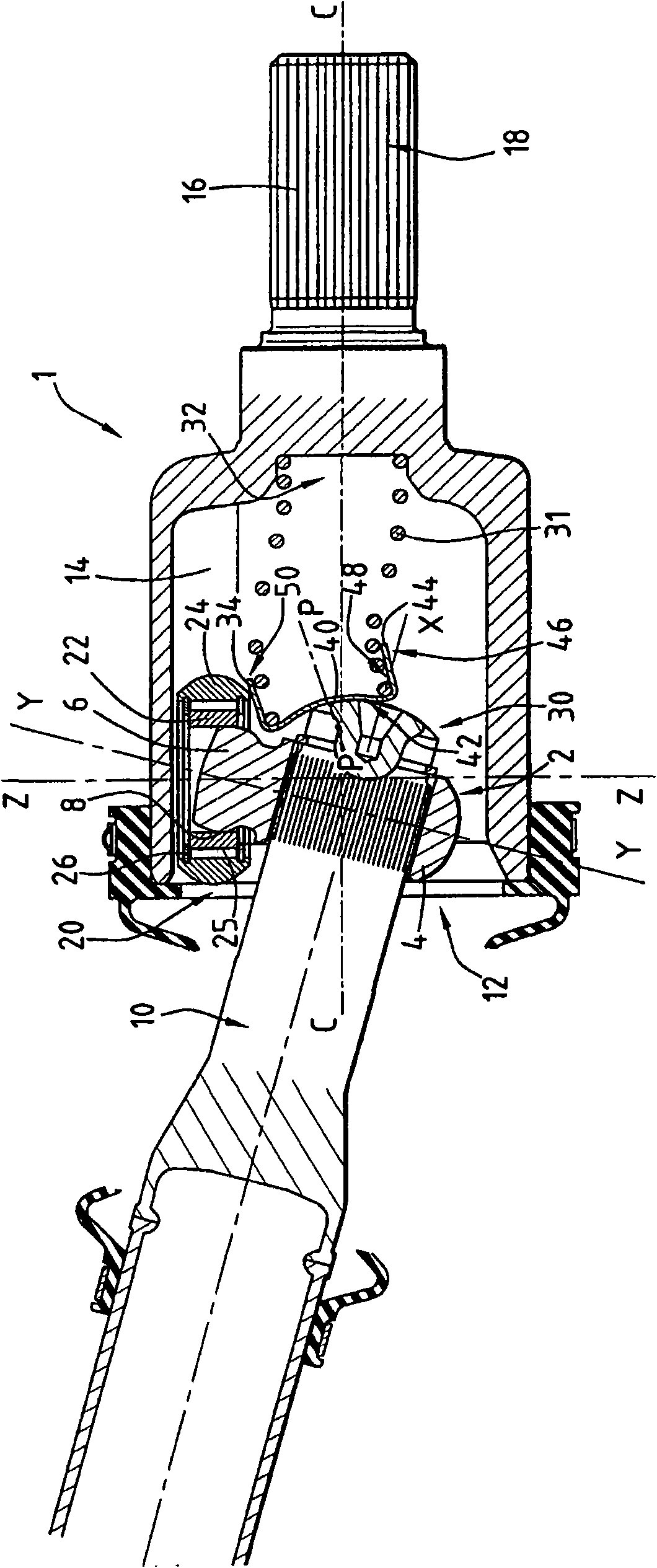
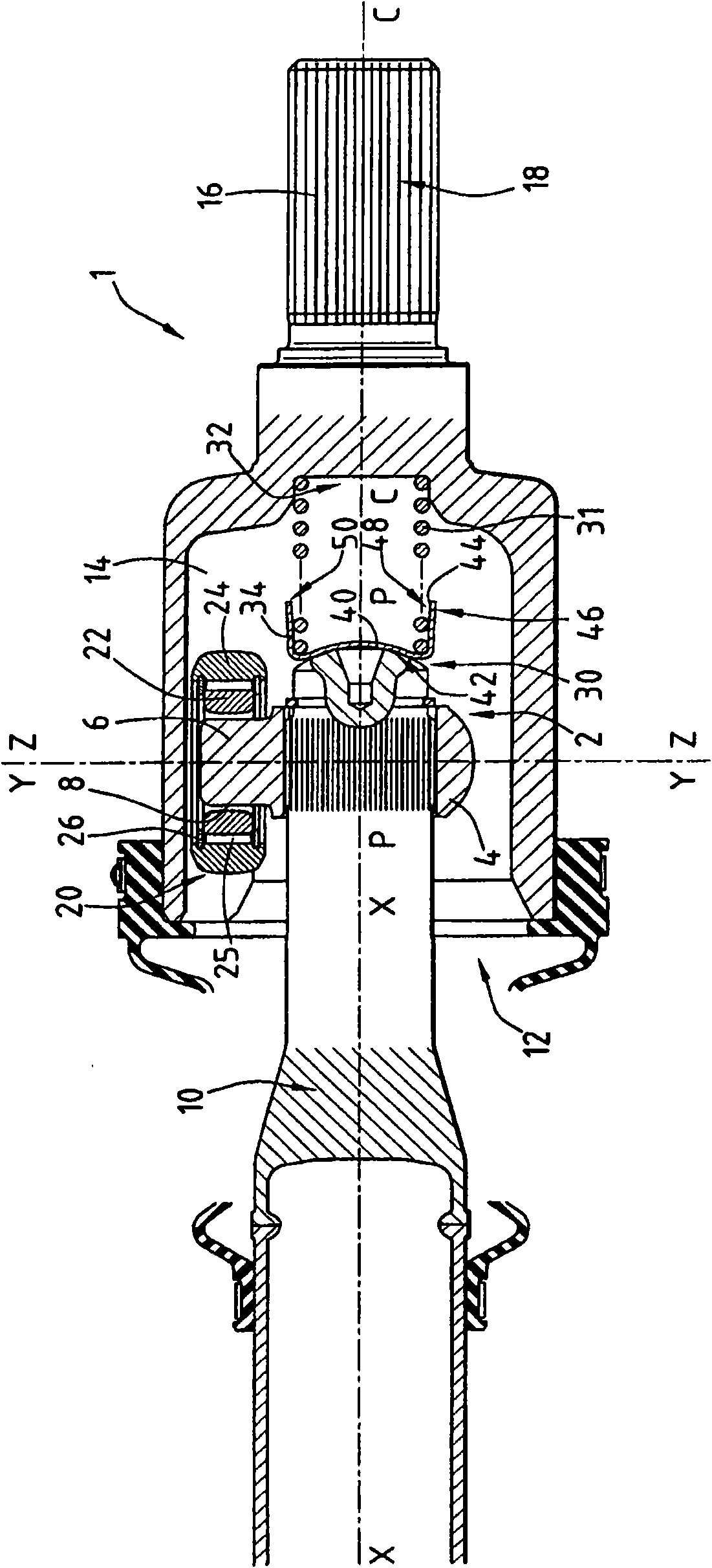
[0026] figure 1 , 2 The shown constant velocity universal joint 1 mainly includes:
[0027] - A male member or tripod 2 with a hub 4 of central axis X-X, from which project three radial arms 6 angularly spaced by 120°. Each arm 6 has its own axis Y-Y. The end of each arm 6 forms a spherical bearing 8 integral therewith and centered on the axis Y-Y of the respective arm 6 . The male member 2 is connected to a first shaft 10 of axis X-X.
[0028] - A female member or socket 12, the central axis C-C of which coincides with the axis X-X in the alignment of the universal joint 1 shown. On either side of each arm 6 , the socket 12 has two opposing rolling tracks 14 . The socket 12 is connected to a second shaft 16 with a keyway 18 .
[0029] - For each arm 6 there is a rolling assembly 20 with axis Z-Z, at figure 1 In the straight-line position of the gimbal shown, this axis Z-Z coincides with the axis Y-Y of the corresponding arm 6 .
[0030] Each rolling assembly 20 includ...
PUM
 Abstract
Description
Claims
Application Information
 - R&D Engineer
- R&D Manager
- IP Professional
- Industry Leading Data Capabilities
- Powerful AI technology
- Patent DNA Extraction
Browse by: Latest US Patents, China's latest patents, Technical Efficacy Thesaurus, Application Domain, Technology Topic, Popular Technical Reports.
© 2024 PatSnap. All rights reserved.Legal|Privacy policy|Modern Slavery Act Transparency Statement|Sitemap|About US| Contact US: help@patsnap.com