
Brush manufacturing machine

A brush making machine and brush bristles technology, which is applied in the direction of brushes, brush bodies, household appliances, etc., to achieve the effect of reducing space requirements

Inactive Publication Date: 2009-10-21
ZAHORANSKY AG
View PDF1 Cites 7 Cited by
  • Summary
  • Abstract
  • Description
  • Claims
  • Application Information

AI Technical Summary

Problems solved by technology

Does not require expensive and complex intermediate storage

Method used


Image

  • Brush manufacturing machine
  • Brush manufacturing machine

Examples


Embodiment Construction

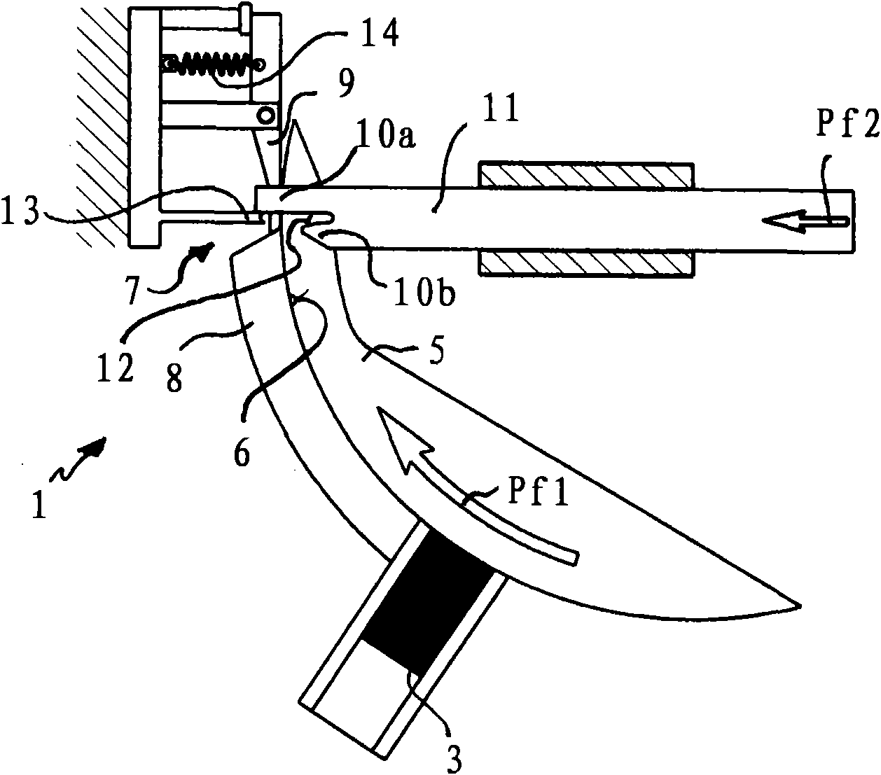
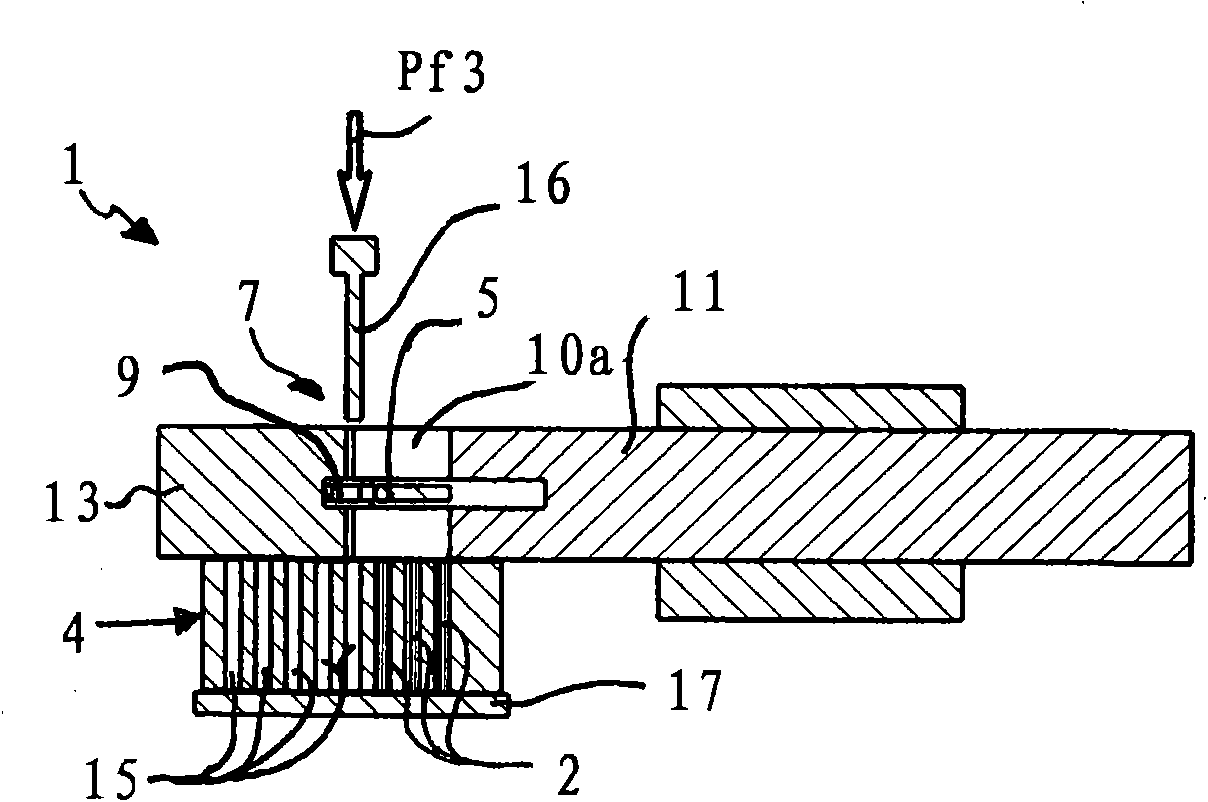
[0020] According to the accompanying drawings, the brush making machine has a device for removing the bristle bundle 2 from the bristle storage device 3 ( figure 1 ) to a box in the form of ( figure 2 ) of the bristle receiving portion 4 of the bristle delivery device 1 . Such as figure 1 As shown, the bristle delivery device 1 comprises a beam splitter 5 with a receiving groove 6 for removing bristle bundles from the bristle storage device 3 . To this end, the beam splitter 5 can be pivoted between a beam receiving position in which the receiving groove 6 is arranged in the region of the bristle storage device 3 and a bundle output position in which the receiving groove 6 is arranged in the region of the loading position 7 (arrow Pf1 ).

[0021] The beam splitter 5 is guided on an edge cover 8 which covers the receiving groove 6 during transport of the bristle bundles and thus holds the bristle bundles in the receiving groove 6 . In the region of the loading point 7 , a ...


PUM


Abstract

The present invention relates to a brush manufacturing machine having a bristle conveying device (1) from a bristle storing device (3) to a box or a bristle receiving section (4), the bristle receiving section has a receiving opening (15) for single bristle bundle, wherein the machine has a bundle divider with a receiving notch (6) for fetching out the bristle bundle from the bristle storing device (3). In a zone with a assembly point (7), a bundle slider (11) capable of moving between a conveying position and a retaining position is provided to convey the bundle (2) from the bundle divider (5) to the bristle receiving section (4), the slider is used for removing the bristle bundle (2) from the receiving notch (6) of the bundle divider (5) and holding the bristle bundle (2) between the bundle slider (11) and a bundle holder (13). An axially adjustable ejector (16) is also provided to loading and discharging the bristle bundle (2), held between the slider (11) and the bundle holder (13), into and from the bristle receiving section (4).

Description

technical field [0001] The invention relates to a brush making machine comprising a bristle delivery device from a bristle storage device to a box with receiving openings for individual bristle tufts or a similar tuft receptacle, wherein the brush making machine comprises a separate A bundler for taking out the bristle bundles from the bristle storage device. Background technique [0002] Brush-making machines of the type mentioned at the outset are known in various designs. A brush-making machine is known in which the bristle bundles taken out of the bristle storage device by means of a beam splitter are fed to an implanting tool / filling tool (Stopfwerkzeug), folded roughly in the center and then implanted with an anchoring platelet. into the brush body. [0003] Brushes are usually also processed without anchoring and without folding in the so-called in-molding method by inserting the bristle bundles into boxes or perforated plates with openings for receiving the bristle...

Claims


Application Information

Patent Timeline
Patent Type & Authority Applications(China)
IPC IPC(8): A46D3/00A46D3/08
CPCA46D3/04
Inventor B·雷斯
Owner ZAHORANSKY AG
Learn More