
Method and apparatus for fitting or removing a motor vehicle tyre

A wheel and tire technology, used in tire installation, vehicle parts, tire parts, etc.

Active Publication Date: 2009-10-21
SNAP ON EQUIP
View PDF6 Cites 14 Cited by
  • Summary
  • Abstract
  • Description
  • Claims
  • Application Information

AI Technical Summary

Problems solved by technology

In this case, the tool performs a relatively complex movement according to the various corrections involved in relation to the corresponding wheel type

Method used


Image

  • Method and apparatus for fitting or removing a motor vehicle tyre
  • Method and apparatus for fitting or removing a motor vehicle tyre
  • Method and apparatus for fitting or removing a motor vehicle tyre

Examples


Embodiment Construction

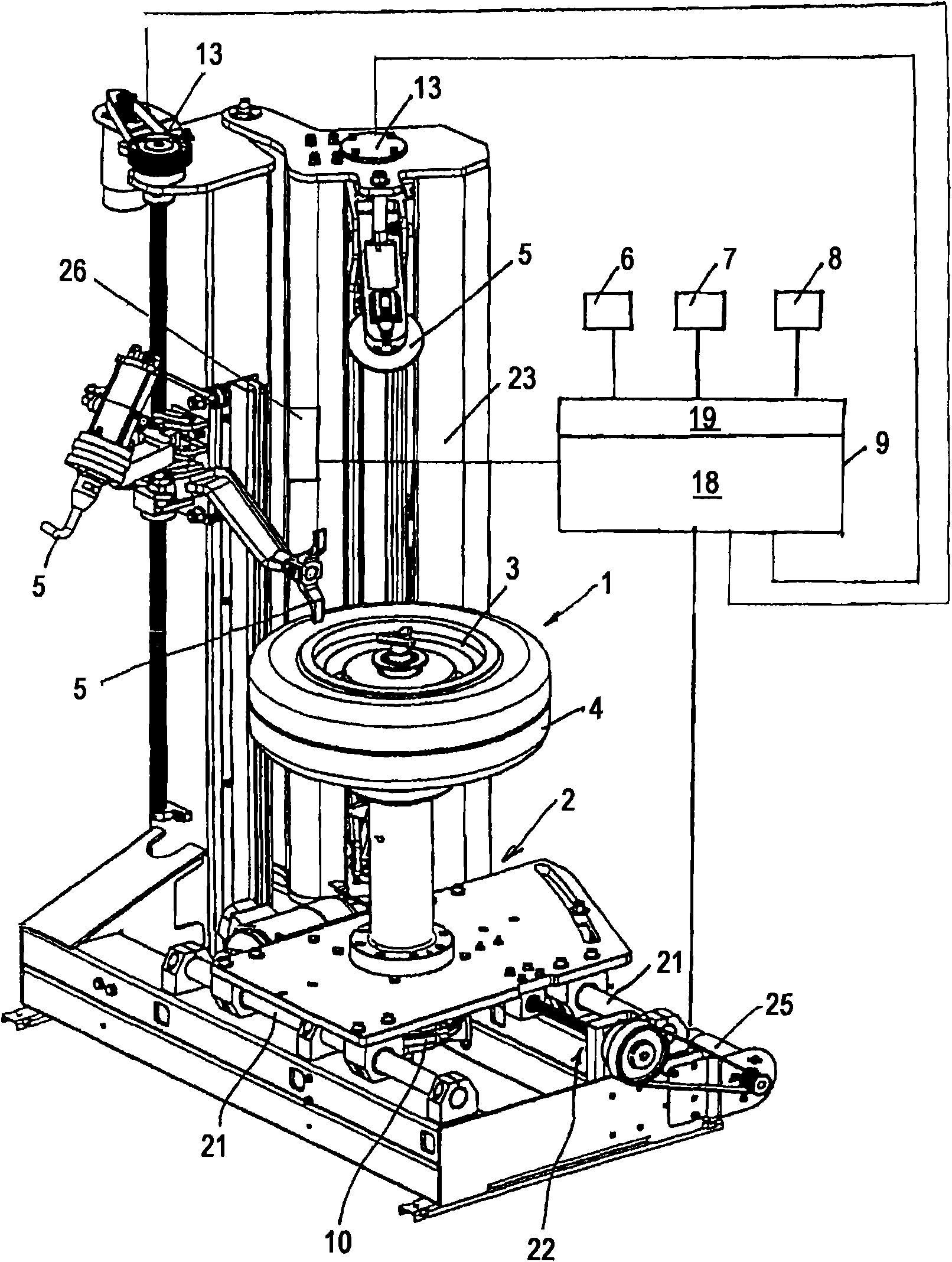
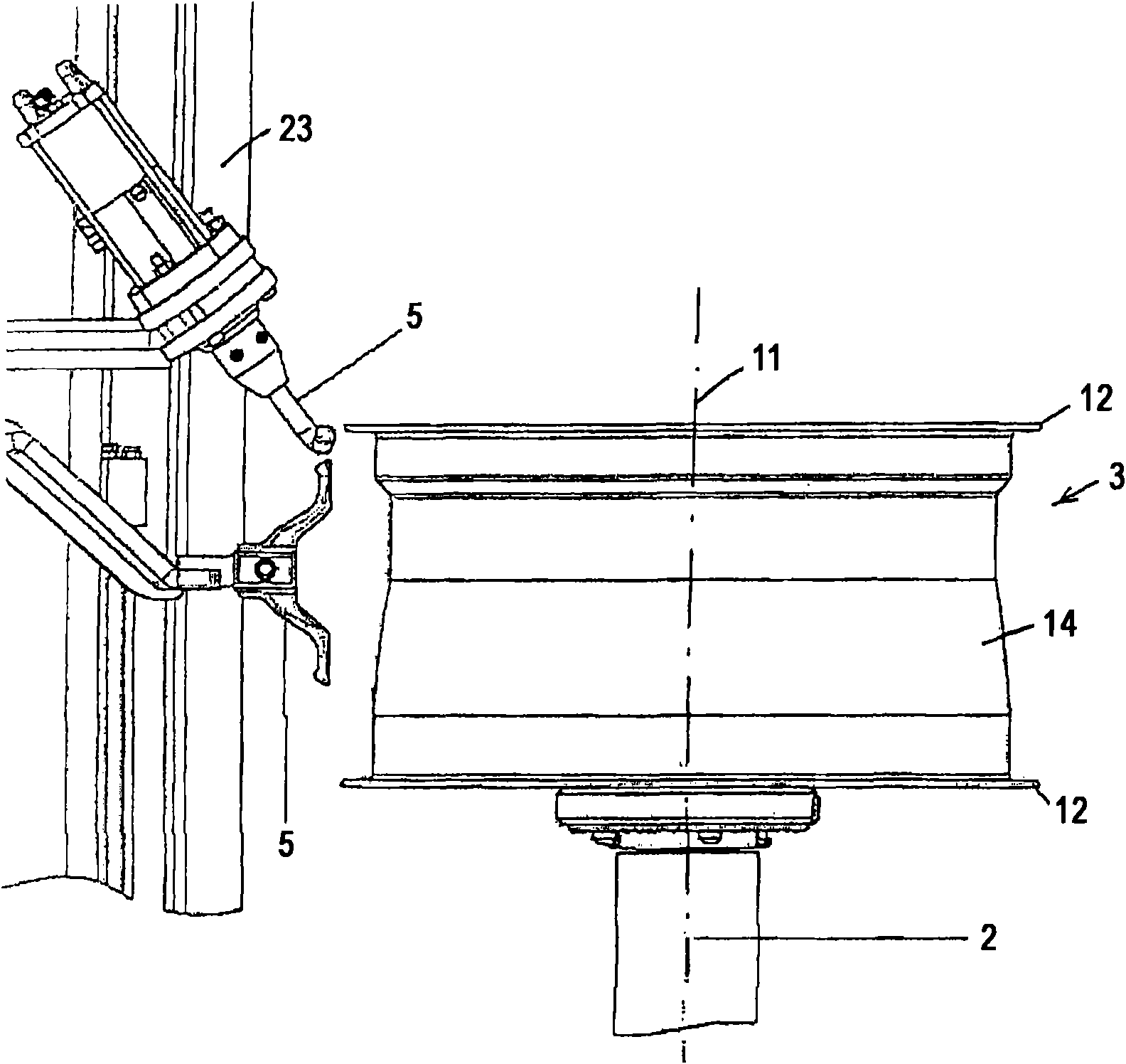
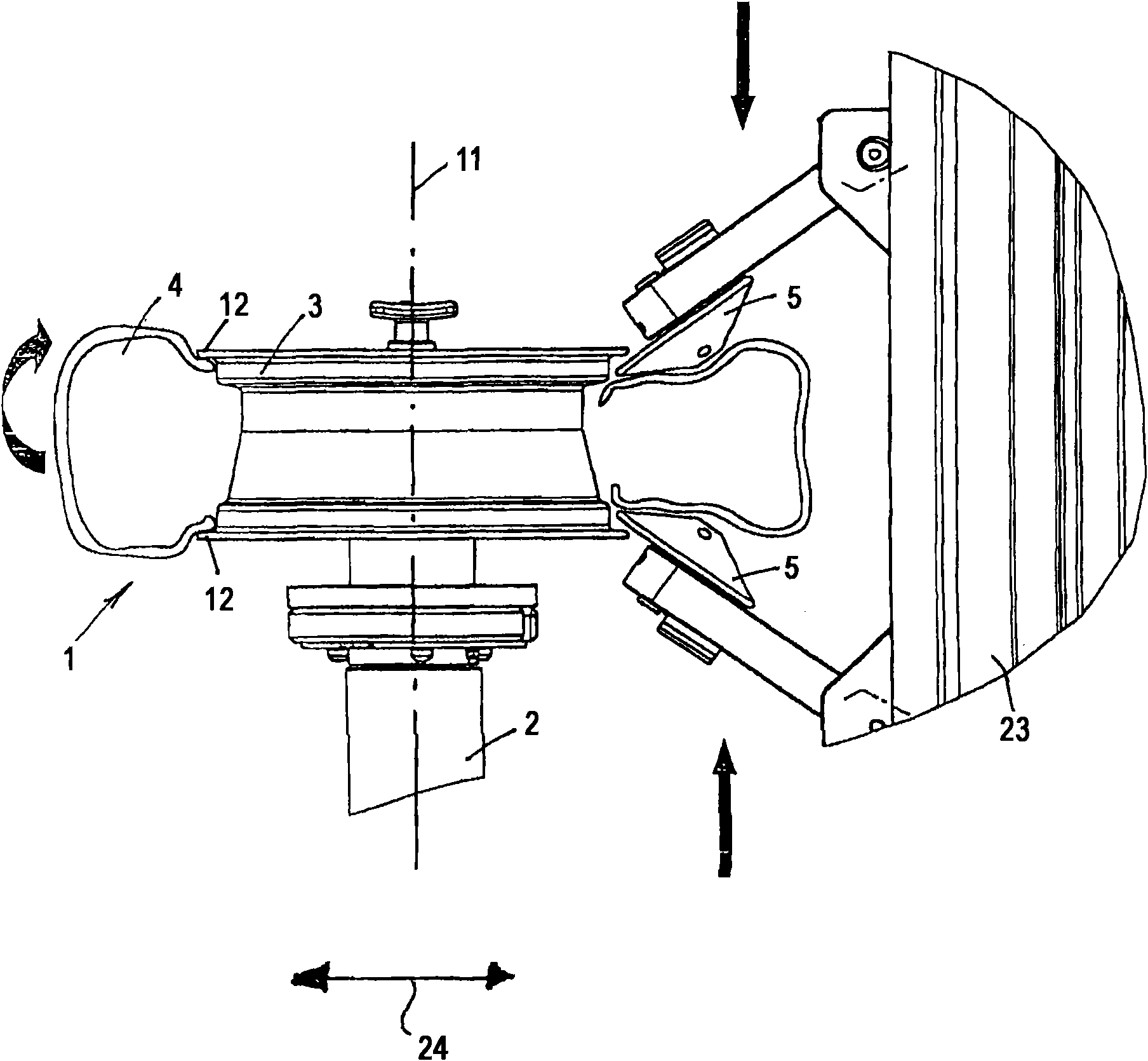
[0017] exist figure 1 The embodiment shown as an example comprises a wheel mounting device 2 to which a rim of a vehicle wheel 1 can be fastened. The wheel mounting device 2 can be a known structure. The rim 3 is connected to the wheel mounting device 2 in a non-rotatable relation to the wheel mounting device 2 and in a central relation to the axis 11 of the wheel by means of fixed means, in particular clamping means. The wheel mounting device 2 is driven in rotation by means of a rotary drive device 10, which may be in the form of an electric motor. In this case, the rotational drive is about the axis 11 of the wheel ( figure 2 with image 3 ).

[0018] In the illustrated embodiment, as Figure 4 As briefly shown in , the optical device sensing devices 6 , 7 and 8 may be arranged for sensing the rim profile at the peripheral surface of the rim 3 . The sensing devices 6 and 7 serve to sense the rim contour in the region of the rim flange 12 , while the sensing device 8 ...


PUM


Abstract

The invention discloses a method of and an apparatus for fitting or removing a tyre (4) of a vehicle wheel (1), in which at least one fitting or removal tool (5) is guided parallel to the axis (11) ofthe vehicle wheel (1) and the vehicle wheel (1) is moved controlledly perpendicularly to its wheel axis (11) in dependence on a rim contour along which the fitting or removal tool (5) is to be guidedat a small spacing.

Description

technical field [0001] The present invention relates to a method and a device for mounting a tire on or removing a tire from the rim of a wheel. Background technique [0002] For this purpose it is known from US Pat. No. 3,877,505 to provide sensing means on the mounting or removal tool in the form of projections, eg made of plastic material, for sensing the radially outer surface (rim saddle). This ensures that the tool is held at a given distance from the rim surface and that the rim surface is not damaged by the hard material of the tool during the tire mounting or demounting operation. [0003] It is further known from DE2529343B2 to move a tire fitting or removal tool along a control surface, which ensures that the tool is guided along the rim contour in the rim saddle. In this case, different control surfaces must be provided depending on the different wheel types involved. [0004] It is further known from US 2004 / 0165180 A1 to acquire one or more optical images of ...

Claims


Application Information

Patent Timeline
Patent Type & Authority Applications(China)
IPC IPC(8): B60C25/02B60C25/04
CPCB60C25/135B60C25/0527Y10T29/49494
Inventor P·索特吉
Owner SNAP ON EQUIP
Learn More