
Locking catch block
A technology of locking buckles and spacers, which is applied in the direction of floors, buildings, building structures, etc., can solve the problems of not being able to reach the wooden floor and ensure that the wooden floor is not deformed, so as to improve the installation quality, facilitate disassembly and maintenance, The effect of preventing deformation
- Summary
- Abstract
- Description
- Claims
- Application Information
AI Technical Summary
Problems solved by technology
Method used
Image

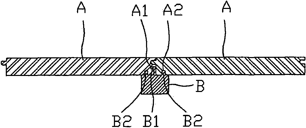
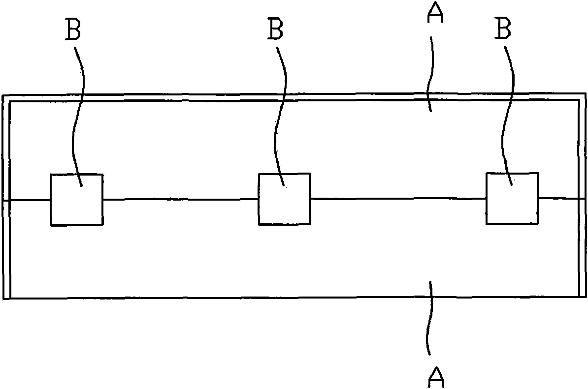
Examples
Embodiment 1
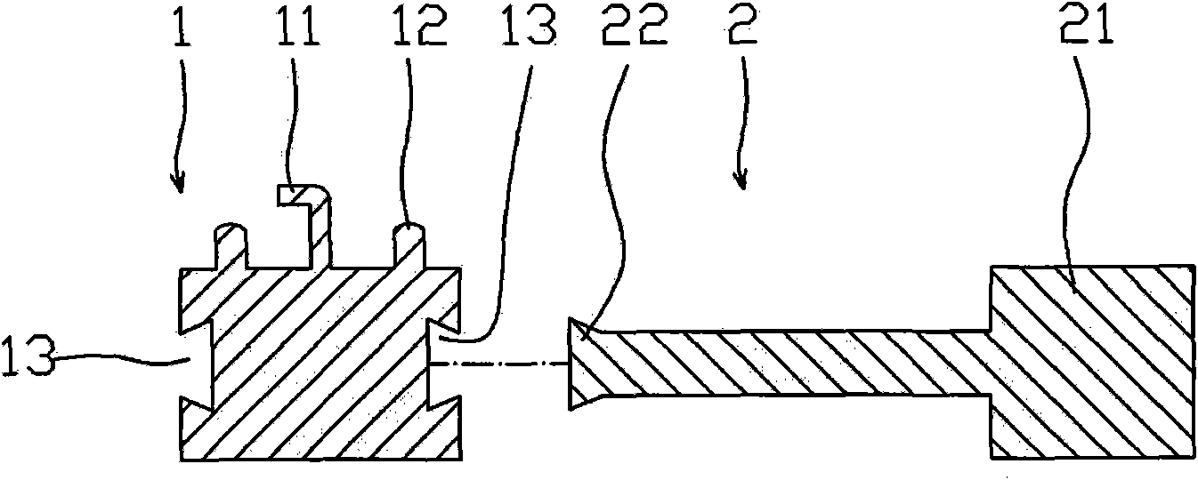
[0047] Example 1, see image 3 , Figure 10 , locking buckle block, including keel 1, spacer 2, the upper middle of keel 1 has ribs 11 with barbs, ribs 12 distributed on both sides of ribs 11 with barbs, keel 1 is formed with Insertion slot 13, spacer 2 is composed of a main body 21 with the same height as the keel 1 cube and an insertion tenon 22 matched with the insertion groove 13 on the keel 1, and the insertion tenon 22 on the spacer 2 is inserted into the In the insertion slot 13 on the keel 1.
[0048] The section of the rib 11 with the barb is in the shape of "7"
[0049] The ribs 12 on the two sides are symmetrically distributed on the two sides of the ribs 11 with barbs.
[0050] Screw fixing holes 14 are formed on the keel 1 .
[0051] The insertion slot 13 is dovetail-shaped
[0052] The insertion slot 13 is a horizontal insertion slot.
[0053] See Figure 12 , 13 , the fixture used in conjunction with the locking buckle block, one side of the block body 3...
Embodiment 3
[0055] Example 3, see Figure 5 , the cross-section of the rib 11 with barbs is or "F" shape.
[0056] All the other are with embodiment 1.
Embodiment 4
[0057] Example 4, see Figure 6 , The insertion slot 13 is T-shaped, and the corresponding insertion tenon 22 is T-shaped.
[0058] All the other are with embodiment 1.
PUM
 Abstract
Description
Claims
Application Information