Pin-hole main and auxiliary fin buckling board

A technology of auxiliary ribs and locking plates, which is applied to floors, coverings/linings, buildings, etc., can solve the problems of easily damaged house structures, high stress on wooden floors, and deformation of wooden floors, so as to improve installation quality, facilitate maintenance, Fast installation effect

Inactive Publication Date: 2007-04-04
李新发
View PDF0 Cites 1 Cited by
  • Summary
  • Abstract
  • Description
  • Claims
  • Application Information

AI Technical Summary

Problems solved by technology

[0002] The traditional wooden floor is composed of wooden boards and keels. There are yin and yang grooves between adjacent two wooden boards. The keel is usually made of square wooden strips. In fact, this is not only complicated to install, it is easy to damage the structure of the house, but it will also cause excessive stress on the wooden floor, which is likely to cause deformation of the wooden floor

Method used


Image

  • Pin-hole main and auxiliary fin buckling board
  • Pin-hole main and auxiliary fin buckling board
  • Pin-hole main and auxiliary fin buckling board

Examples


Embodiment 1

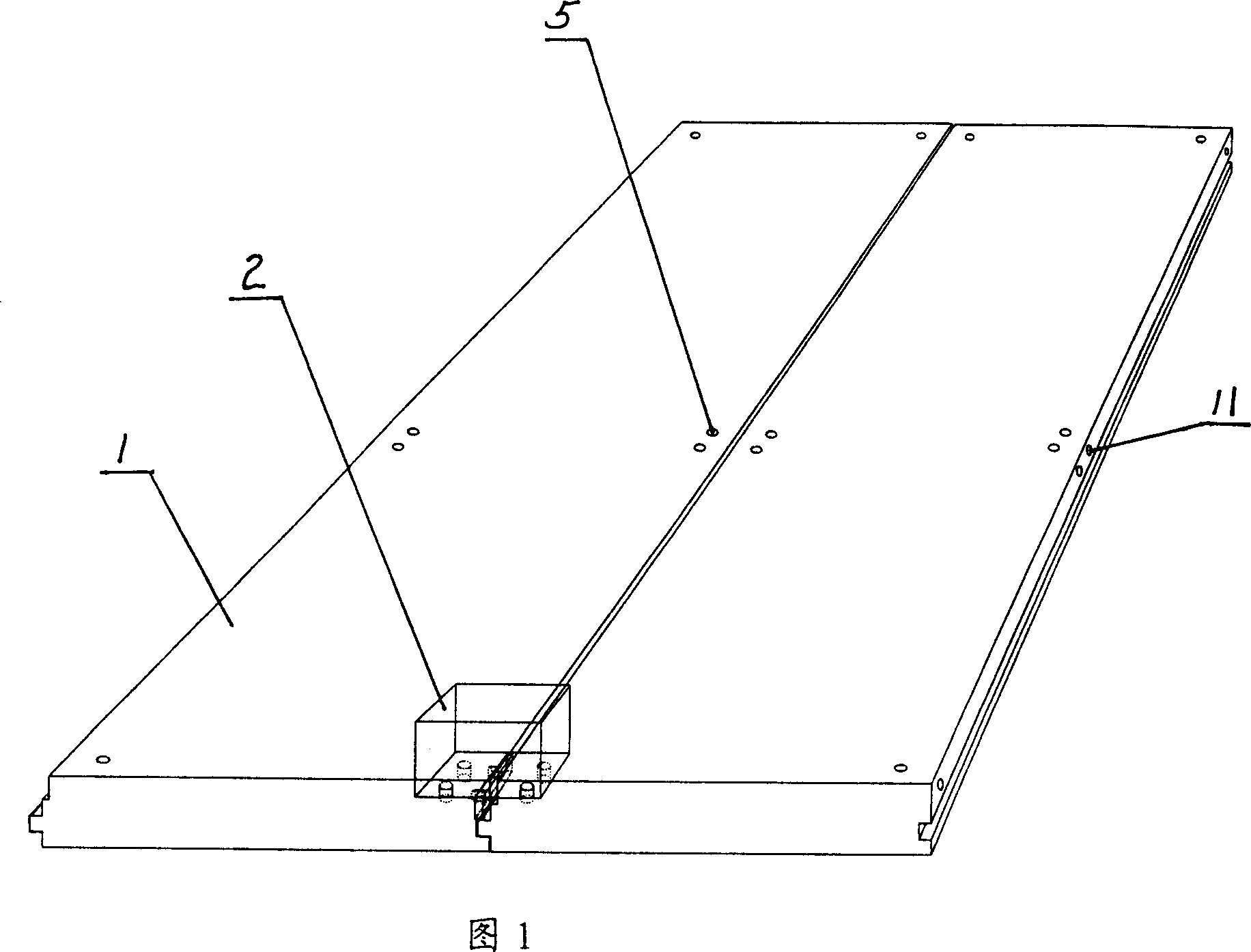
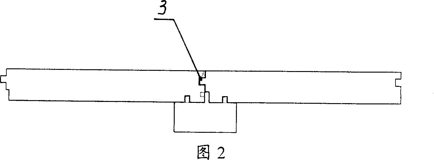
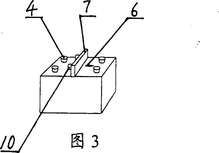
[0022] Embodiment 1: Refer to Figs. 1 to 3. This embodiment is composed of a plate 1 and a keel 2. The two adjacent plates 1 are matched by the main rib 7 and the female and male grooves 3. The surface of the keel 2 is provided with two rows of auxiliary ribs arranged in parallel, and each row of auxiliary ribs consists of two pins. The shaft 4 is composed of two pin holes 5 matched with the above-mentioned pin shaft 4 on each side plate 1 on the back of the two side plates at the splicing seam of adjacent plates. The main rib 7 is arranged between the two rows of auxiliary ribs, and is parallel to each row of auxiliary ribs. A protruding main rib connecting body is provided on the left side wall of the main rib 7 and the main rib connecting body is composed of two main rib pins 10. A main rib pin hole 11 matched with the above-mentioned main rib pin shaft 10 is provided on the butt joint end surface of the joint of two adjacent plates 1.

Embodiment 2

[0023] Embodiment 2: Refer to Figures 4 to 6. This embodiment is composed of a plate 1 and a keel 2. The adjacent two plates are joined together by the main rib 7 and the male and female grooves 3. On the surface of the keel 2, there are two rows of auxiliary ribs arranged in parallel, and the main ribs 7 are arranged in two rows. Between the auxiliary ribs, parallel to each row of auxiliary ribs. A row of auxiliary ribs located on the left side of the main rib 7 is composed of two pin shafts 4, and a row of auxiliary ribs located on the right side of the main rib 7 is composed of strip-shaped convex ribs 9. A pin hole 5 matched with the above-mentioned pin shaft 4 and a groove 8 matched with the above-mentioned strip-shaped rib 9 are respectively provided on each side plate 1 on the back of the two side plates at the splicing seam of adjacent plates. A protruding main rib connecting body is provided on each side of the left and right side walls of the main rib 7 and the main rib ...

Embodiment 3

[0024] Embodiment 3: Refer to Figs. 7-9. This embodiment is composed of a plate 1 and a keel 2, and the main ribs 7 and the female and male grooves 3 are matched and spliced ​​together between the two adjacent plates. Two rows of auxiliary ribs arranged in parallel are arranged on the surface of the keel 2, and the main ribs 7 are arranged between the two rows of auxiliary ribs and are parallel to each row of auxiliary ribs. A row of auxiliary ribs located on the left side of the main rib 7 is composed of two pin shafts 4, and a row of auxiliary ribs located on the right side of the main rib 7 is composed of strip-shaped convex ribs 9. A pin groove 13 matching the pin shaft 4 of the keel 2 and a groove 8 matching the strip-shaped rib 9 of the keel 2 are respectively provided on each side panel 1 on the back of the two side panels at the splicing seam of adjacent panels. A protruding main rib connecting body is provided on each side of the left and right side walls of the main rib ...


PUM


Abstract

The invention relates to a pinhole main tendon and assistant tendon locked up dy lock, it is composed of board and keel, the characteristic is two proximate board joined in keel, on the surface of keel ,setting up a main tendon, either of the two side of the main tendon have a juncture connect main tendon at least, the juncture of the main tendon composed of a pin roll at least which parallel on juncture of proximate board, on the buttcove surface which the two proximate board before-mentioned set up a connected groove matched with forelock before-mentioned, both side of the keel surface of the main tendon, each side of surface have a assistant tendon which parallel on main tendon, at least have a assistant tendon is composed of pin roll which parallel on juncture proximate board, on the two side of main tendon ,in which assisant tendon of surface keel,have setting a connected groove matched with assisant tendon. The invention is very facility to install, no need of glue,nail and plywood, the technics is simple, it's very fast to install, and when install there is no noise,powder and garbage.

Description

Technical field [0001] The invention relates to a decorative board, in particular to a pin-hole type main rib and auxiliary rib locking plate suitable for use as floors, wall plates and ceilings. Background technique [0002] Traditional wooden floor is composed of wooden planks and keels. Two adjacent wooden planks are matched by yin and yang grooves. The keel is usually made of square wooden slats. When using, the wooden slats are nailed to the ground and the wooden floor is nailed to the square wooden slats In this way, not only the installation is complicated, it is easy to damage the structure of the house, but also it will cause excessive stress on the wooden floor, which is easy to cause deformation of the wooden floor. Summary of the invention [0003] The purpose of the present invention is to solve the deficiencies of the above-mentioned background technology, and propose a pin-hole type main rib and auxiliary rib locking plate that can be repeatedly disassembled and a...

Claims


Application Information

Patent Timeline
Patent Type & Authority Applications(China)
IPC IPC(8): E04F13/076E04F13/24E04F15/02
Inventor 李新发
Owner 李新发
Why Eureka
Try Eureka