Electric lock

A technology of electric locks and motors, which is applied in the field of electric locks, and can solve the problems of damage to the screw micro-motor and failure to lock.

Active Publication Date: 2009-10-21
青岛博宁福田通道设备股份有限公司
View PDF2 Cites 6 Cited by
  • Summary
  • Abstract
  • Description
  • Claims
  • Application Information

AI Technical Summary

Problems solved by technology

In this patent application, the lead screw directly drives the lock tongue, and there is no buffer mechanism when the lock tongue is stretched out. If the lock tongue cannot accurately enter the lock hole when the lock tongue is stretched out, the lock tongue will be blocked, which may damage the lead screw or the micro-motor. And you can't lock the doors, windows, etc. that need to be locked

Method used


Image

  • Electric lock
  • Electric lock
  • Electric lock

Examples


Embodiment Construction

[0032] Embodiments of the present invention will be described in detail below in conjunction with the accompanying drawings.

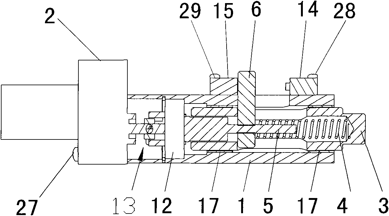
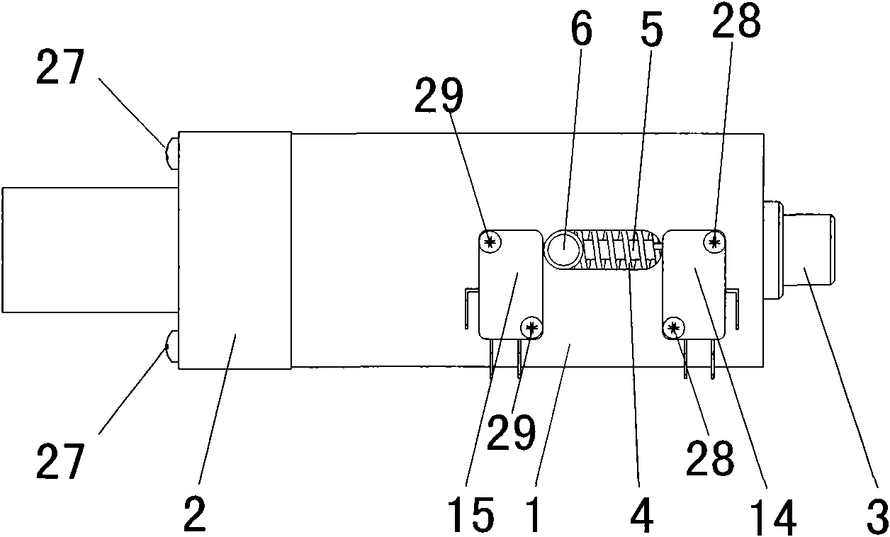
[0033] Such as Figure 1 to Figure 12As shown, the present embodiment is an electric lock for a revolving door, which includes a lock body 1 , a motor 2 , a deadbolt 3 , a driving device, a spring 4 and a control circuit for the motor 2 . The lock body 1 has a hole 7 in which a bushing 17 is installed. Bushing 17 has two before and after altogether, and they adopt brass to make. The hole 7 of the lock body 1 is a circular hole, the outer surface of the bushing 17 is a cylindrical surface, and the outer surfaces of the two bushings 17 and the hole 7 of the lock body 1 adopt an interference fit. The bushing 17 has a circular hole 18, and the diameters of the circular holes 18 of the two bushings 17 are equal and coaxial. The outer surface of the dead bolt 3 is a cylindrical surface, and the dead bolt 3 is sleeved in the circular holes 18 of the two bu...


PUM


Abstract

The invention relates to an electric lock named as an electric lock and aims at solving the technical problem that as no buffer gear exists between a bolt and a guide screw of the existing electric lock, the guide screw or a micro motor is easy to be damaged. The technical scheme of the invention is as follows: the electric lock comprises a lock body 1, a motor 2 and a bolt 3 which can extend outof or retract into the lock body. The output shaft of the motor 2 is connected with a driving device, and a spring 4 is arranged between the driving device and the bolt 3. If the bolt 3 is obstructedwhen extending out of the lock body 1, the spring 4 has buffer effect, thus protecting the motor 2 and the driving device from being damaged.

Description

Technical field: [0001] The invention relates to an electric lock. Background technique: [0002] On June 21, 2006, an invention patent application called a remote control electric lock was disclosed in the Invention Patent Bulletin, the application number is: 200510045546.X, and the publication number is: CN1789646. This patent application remote control electric lock comprises a lock body and a dead bolt that can extend or retract into the lock body. There is a micro-motor in the lock body, the output end of the micro-motor is provided with a lead screw, and the rear end of the deadbolt is located in the lock body and a thread hole is provided, and the lead screw matches the thread hole and can be driven by the micro-motor to push the dead bolt out or Indent the lock body. In this patent application, the lead screw directly drives the lock tongue, and there is no buffer mechanism when the lock tongue is stretched out. If the lock tongue cannot accurately enter the lock h...

Claims


Application Information

Patent Timeline
Patent Type & Authority Applications(China)
IPC IPC(8): E05B47/06E05B15/00
Inventor 夏继华
Owner 青岛博宁福田通道设备股份有限公司
Why Eureka
Try Eureka