T-shaped photonic crystal power divider

A power divider and photonic crystal technology, which is applied in the field of materials, can solve the problems of low isolation at the output end, and the amplitude-frequency characteristics of the passband are not flat enough to achieve the effect of reducing mutual influence.

Active Publication Date: 2009-10-21
东莞成电创新电子科技有限公司
View PDF0 Cites 23 Cited by
  • Summary
  • Abstract
  • Description
  • Claims
  • Application Information

AI Technical Summary

Benefits of technology

This new type of lightweight optical component called an optofluidic device (OP) can be used for controllably shaping electromagnetic waves based on their properties such as phase or frequency differences caused by changes made along certain parts of it's structure. These devices have improved performance compared to traditional components like lenses that are bulky due to its material composition.

Problems solved by technology

This patented technical problem addressed in this patents relates to improving the performance of optofluidic components used for communication purposes due to their ability to efficiently transmit signals over long distances without being affected from external influences like vibrations caused by environmental factors like temperature variations.

Method used


Image

  • T-shaped photonic crystal power divider
  • T-shaped photonic crystal power divider
  • T-shaped photonic crystal power divider

Examples


specific Embodiment approach 1

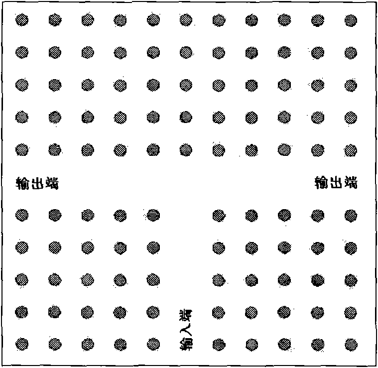
[0019] A photonic crystal T-shaped power divider provided by the present invention is obtained by improving the structure of T-shaped line defects on the basis of the existing photonic crystal T-shaped power divider, such as Figure 4 Shown: Add a dielectric column at the intersection of the vertical line defect and the horizontal line defect of the T-shaped line defect, and remove the medium closest to the added dielectric column at the vertices of the two right-angled corners of the T-shaped line defect column.

specific Embodiment approach 2

[0020] Another photonic crystal T-shaped power divider provided by the present invention is obtained by improving the structure of T-shaped line defects on the basis of the existing photonic crystal T-shaped power divider, such as Figure 5 As shown: a dielectric column is added at the intersection of the vertical line defect and the horizontal line defect of the T-shaped line defect, and a dielectric column is added on the left, right and bottom sides of the dielectric column that is twice the length of the crystal period constant a. At the same time, remove the three dielectric columns closest to the intersection of the vertical line defect and the horizontal line defect at the two right-angle turns of the T-shaped line defect.

[0021] Simulation instructions:

[0022] (1) Improvement of amplitude-frequency characteristics of T-shaped photonic crystal power divider in 1.12THz to 1.22THz frequency band

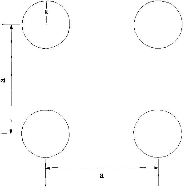
[0023] The designed photonic crystal period a = 100 μm, and the single...


PUM


Abstract

The invention discloses a T-shaped photonic crystal power divider, which belongs to the technical field of materials, and relates to application technology of photonic crystals. In the invention, based on the prior T-shaped photonic crystal power divider, one dielectric cylinder is added in the intersection of a vertical line defect and a horizontal line defect of a T-shaped line defect, and two dielectric cylinders most close to the added dielectric cylinder in the vertex position of two right-angle corners of the T-shaped line defect are removed respectively at the same time. Other dielectric cylinders can also be respectively added in the positions twice of a crystal cycle length which is constant a, from the added dielectric cylinder on the left side, the right side and the lower side, and three dielectric cylinders most close to the intersection of the vertical line defect and the horizontal line defect at the two right-angle corners of the T-shaped line defect are removed respectively at the same time. The improved T-shaped photonic crystal power divider has the advantages of high amplitude-frequency characteristic flatness in a pass band, reduction of interaction between two output ends of the T-shaped power divider and better practicability.

Description


Claims


Application Information

Patent Timeline
Owner 东莞成电创新电子科技有限公司
Why Eureka
Try Eureka