
Method for detecting capacitive type touch-control device

A technology of capacitive touch and detection method, which is applied in the direction of electrical digital data processing, input/output process of data processing, instruments, etc., can solve problems such as affecting the performance of the application side and reducing the image acquisition speed.

Inactive Publication Date: 2009-10-21
ELAN MICROELECTRONICS CORPORATION
View PDF0 Cites 16 Cited by
  • Summary
  • Abstract
  • Description
  • Claims
  • Application Information

AI Technical Summary

Problems solved by technology

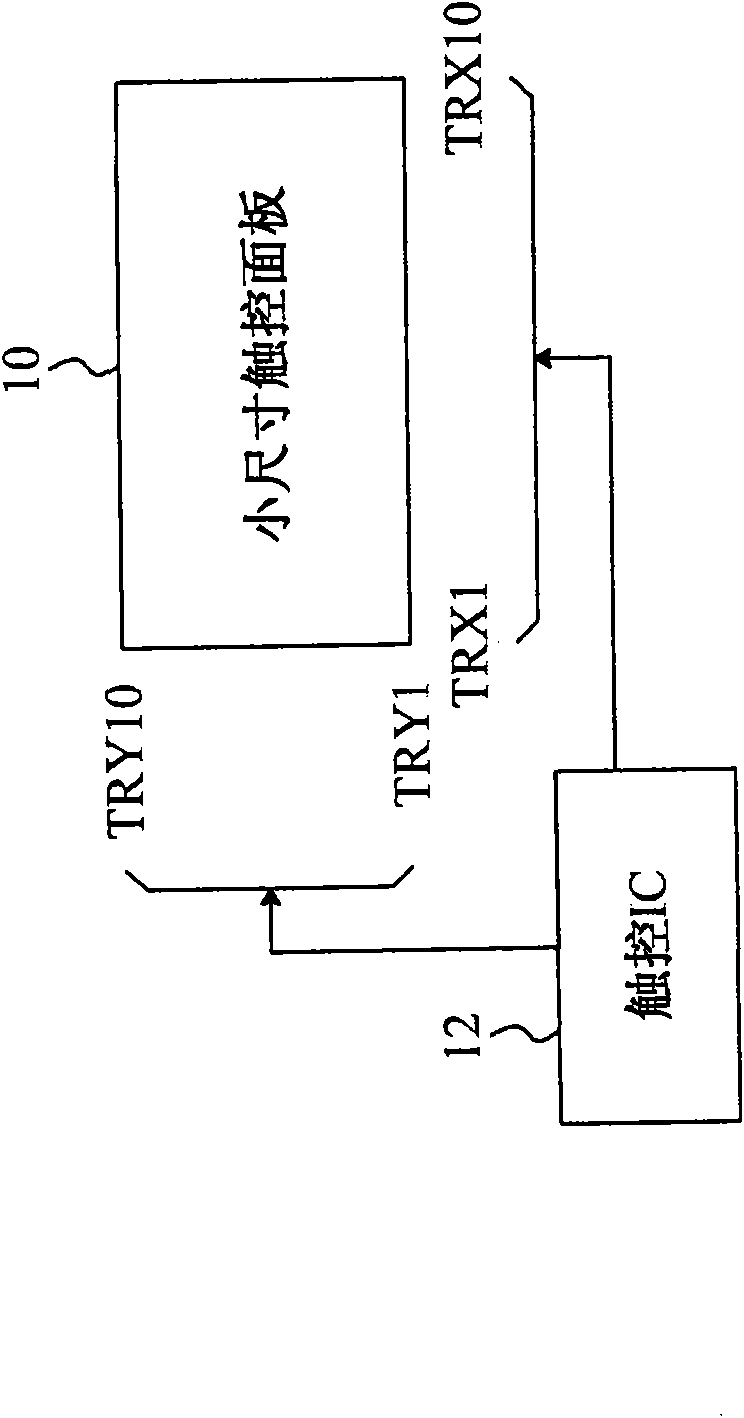
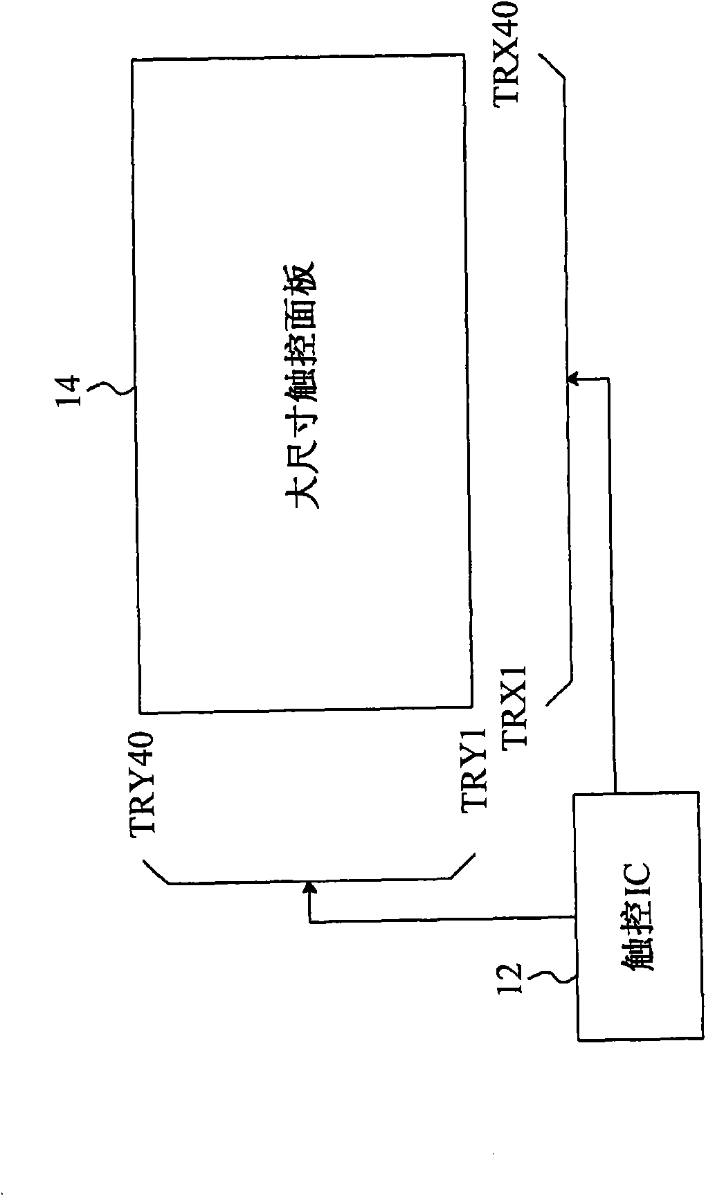
figure 1 It shows the AI-type array capacitive sensing technology traditionally applied to small-size touch panels, which includes a small-size touch panel 10 and an AI-type array capacitive touch IC12 to scan the touch panel 10, with a maximum supportable scanning Take the AI-type array capacitive touch IC12 with 22 sensing lines as an example, although it is applied to a small-sized touch panel with 10 sensing lines TRX1~TRX10 and TRY1~TRY10 on the X-axis and Y-axis respectively, the image acquisition speed is 10 Not bad, but if the AI-type array capacitive touch IC 12 is to be applied to a large-size touch panel 14 with 40 sensing lines TRX1-TRX40 and TRY1-TRY40 on the X-axis and Y-axis respectively, if figure 2 As shown, it is necessary to increase the total number of sensing lines that can be scanned by the AI ​​array capacitive touch IC12. However, the time spent by the touch IC12 on charging and discharging the capacitor each time accounts for the proportion of the image acquisition speed of the overall touch panel application. Very large, that is to say, the imaging speed is mainly determined by the charge and discharge of the capacitor in each frame of IC12, so the method of increasing the number of scannable sensing lines applied to the large-size touch panel 14 will have a very large The disadvantage is that the image acquisition speed of the overall application will be severely reduced, which will affect the performance of the application side.

Method used


Image

  • Method for detecting capacitive type touch-control device
  • Method for detecting capacitive type touch-control device
  • Method for detecting capacitive type touch-control device

Examples


Embodiment Construction

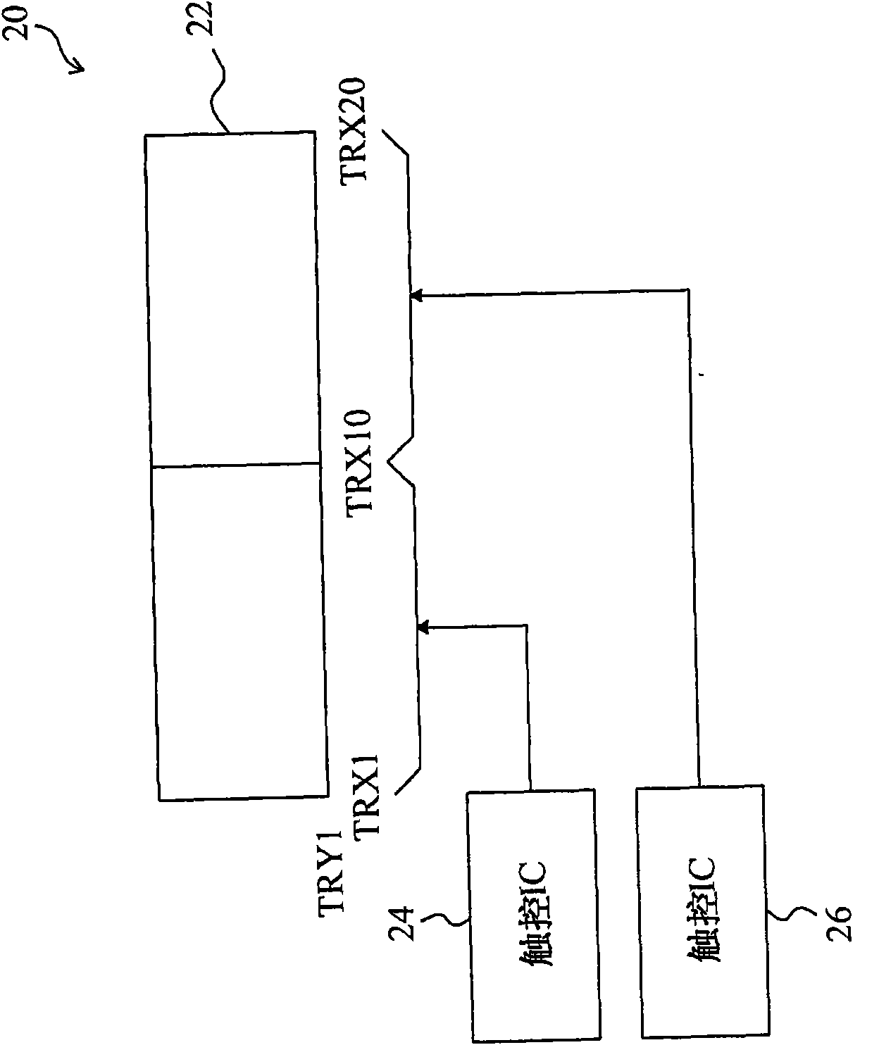
[0026] image 3 It shows a capacitive touch device 20 that uses more than two AI-type array capacitive touch ICs to scan a touch panel. Figure 4 show image 3 A partial enlargement of the . In the capacitive touch device 20 , the touch IC 24 scans the sensing lines TRX1 to TRX10 in the touch panel 22 , and the touch IC 26 scans the sensing lines TRX11 to TRX20 in the touch panel 22 . Since the capacitive touch device 20 can use multiple AI-type array capacitive touch ICs to scan the touch panel at the same time, it not only has a multi-finger touch function but also has a good image capture speed when applied to a large-size panel. In the detection method of the capacitive touch IC of the small-sized touch panel, generally two sensing lines are selected at the same time to charge and discharge the capacitance to obtain the analog-to-digital conversion (Analogy Digital Convert; ADC) value of the two sensing lines. Then use the ADC values ​​of the two sensing lines to obtain...


PUM


Abstract

The invention provides a method for detecting a capacitive type touch-control device. The capacitive type touch-control device comprises a touch-control panel which is provided with a plurality of induction lines, wherein the induction line (N) is connected with a first touch-control integrated circuit, and the induction line (N+1) is connected with a second touch-control integrated circuit. The detecting method comprises the following steps: obtaining an analog-to-digital conversion value of at least one induction line before the induction line (N) and an analog-to-digital conversion value of at least one induction line behind the induction line (N); and deciding the induction capability of the induction line (N) according to the obtained analog-to-digital conversion values. The method for detecting the capacitive type touch-control device is used for judging the induction capability of the induction line (N) in a boundary to avoid the incorrect or smaller condition of the induction capability of the induction line (N) in the boundary.

Description

technical field [0001] The present invention relates to a capacitive touch device, in particular to a detection method of the capacitive touch device. Background technique [0002] In traditional applications, large-size capacitive touch screens use surface capacitive sensing technology, but surface capacitive sensing technology uses a set of currents flowing to each terminal of the screen to determine the position of the finger. When the number of fingers touching the touch panel is more than two fingers, the number of reported current groups is still one, so only one set of absolute coordinate positions can be identified. For example, only one set of X and Y parameters can be reported in a two-dimensional matrix, so The function of multi-finger touch cannot be achieved. [0003] Although the A11 Points Addressable (APA) type array capacitive sensing technology can achieve the function of multi-finger touch, it needs to charge and discharge each point sensor (Point Sensor)...

Claims


Application Information

Patent Timeline
IPC IPC(8): G06F3/044
Inventor 洪泽伦黄荣寿蔡欣学
Owner ELAN MICROELECTRONICS CORPORATION
Learn More