
Wireless receiving and emitting device of mobile communication terminal

Active Publication Date: 2009-10-21
HUIZHOU TCL MOBILE COMM CO LTD
View PDF0 Cites 33 Cited by
  • Summary
  • Abstract
  • Description
  • Claims
  • Application Information

AI Technical Summary

Problems solved by technology

[0008] The purpose of the present invention is to provide a wireless transceiver device for a mobile communication terminal, aiming at solving the problem of optimizing the wireless transceiver performance of a mobile communication terminal

Method used


Image

  • Wireless receiving and emitting device of mobile communication terminal
  • Wireless receiving and emitting device of mobile communication terminal

Examples


Embodiment Construction

[0020] In order to make the object, technical solution and advantages of the present invention clearer, the present invention will be further described in detail below in conjunction with the accompanying drawings and embodiments. It should be understood that the specific embodiments described here are only used to explain the present invention, not to limit the present invention.

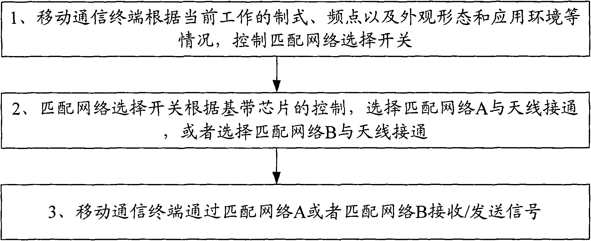
[0021] The system block diagram of the mobile communication terminal wireless transceiver device provided by the embodiment of the present invention is as follows figure 1 As shown, it includes baseband chip (Base Band), radio frequency transceiver (Transceiver), power amplifier module (PA), antenna (Antenna), two or more matching networks (Matching Network) ( figure 1 Take matching network A and matching network B as examples) and matching network selection switch (Matching Network Selector). Among them, the baseband chip is connected with the radio frequency transceiver through the data line and...


PUM


Abstract

The invention is applicable to the field of mobile communication technology and provides a wireless receiving and emitting device for a mobile communication terminal. The wireless receiving and emitting device comprises a baseband chip, a radiofrequency receiving and emitting device, a power amplification module and an antenna; the wireless receiving and emitting device also comprises a network selection switch and two or more matching networks, wherein the wireless receiving and emitting performance indexes of the two or more matching networks correspond to different working modes of the mobile communication terminal; the network selection switch is used for selecting one out of the two or more matching networks and the selected matching network is controlled to be communicated with the antenna. The technical proposal leads the mobile communication terminal to have optimum wireless performance under various application environments, improves the client satisfaction degree and is alsohelpful for optimizing the mobile network and improving the network capability.

Description

technical field [0001] The invention belongs to the technical field of communication, in particular to a wireless transceiver device for a mobile communication terminal. Background technique [0002] Most of the existing mobile communication terminals use built-in antennas, and the application environment of built-in antennas has become more and more severe, which is mainly reflected in the following aspects: [0003] 1. Dual-mode or even multi-mode mobile communication terminals have become more and more popular. Typically, there are 3G and GSM dual-mode mobile communication terminals, which require antennas to work in multiple frequency bands. For the GSM standard alone, mobile communication terminals have been required to start supporting Up to Quad-band (supporting GSM850 / EGSM / DCS / PCS 4 GSM frequency bands at the same time), which puts forward high requirements for multi-frequency and broadband antennas. [0004] 2. Mobile communication terminals are increasingly pursui...

Claims


Application Information

Patent Timeline
Patent Type & Authority Applications(China)
IPC IPC(8): H04B1/38H04B1/18H04W88/06
CPCH04W48/18H04B1/18H03H7/40H04W88/06
Inventor 白剑
Owner HUIZHOU TCL MOBILE COMM CO LTD
Learn More