Substrate positioning device and method, substrate processing device and method

The technology of a positioning device and positioning method is applied in the direction of assembling printed circuits with electrical components, rotary printing machines, printing, etc., which can solve problems such as clamping force deviation, and achieve the effect of high positioning accuracy and increased processing accuracy

Active Publication Date: 2009-10-28
FUJI MASCH MFG CO LTD
View PDF2 Cites 8 Cited by
  • Summary
  • Abstract
  • Description
  • Claims
  • Application Information

AI Technical Summary

Problems solved by technology

Therefore, the clamping f

Method used


Image

  • Substrate positioning device and method, substrate processing device and method
  • Substrate positioning device and method, substrate processing device and method
  • Substrate positioning device and method, substrate processing device and method

Examples


no. 1 approach

[0087] The structure of the screen printing machine

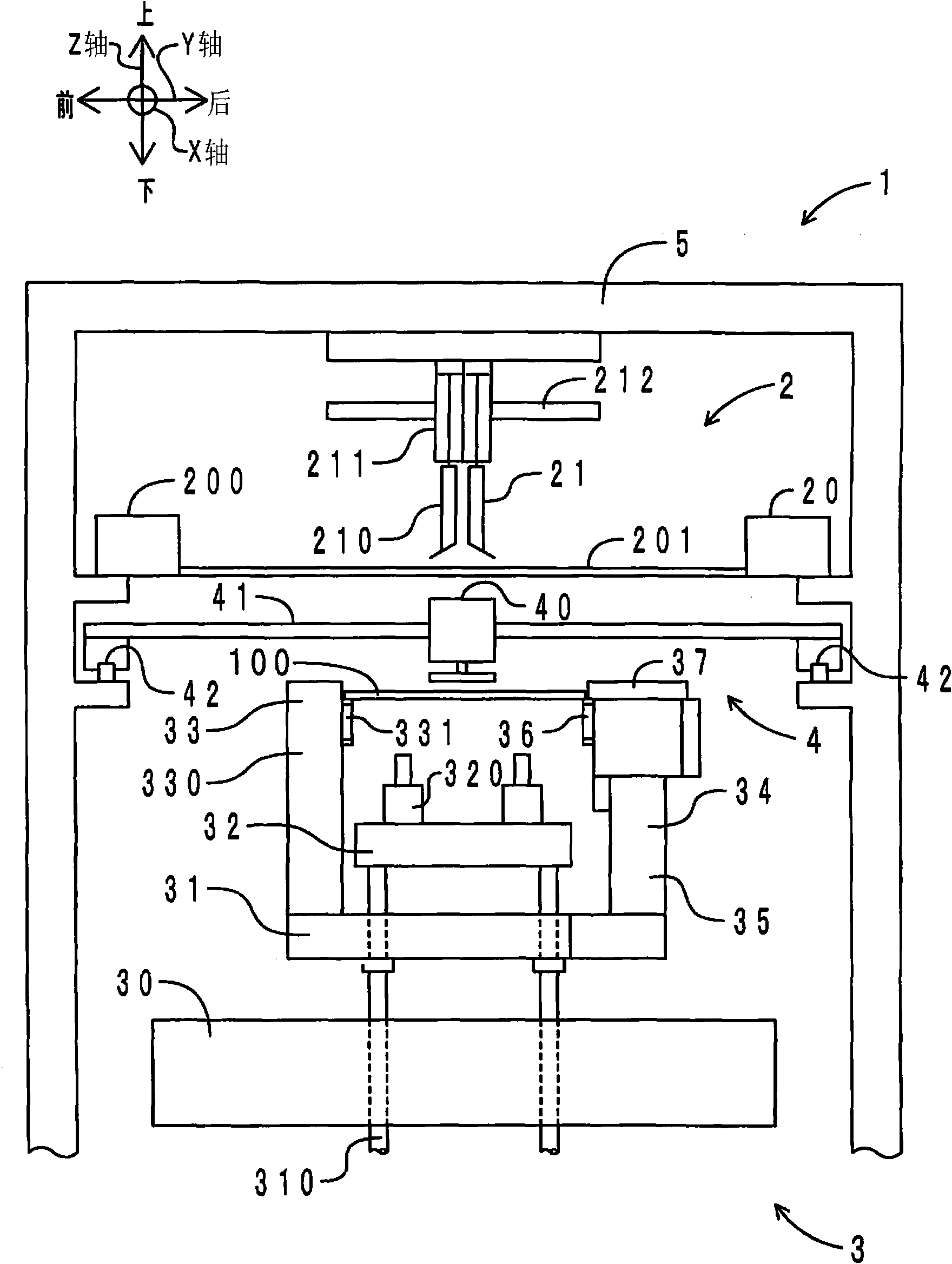
[0088] First, the structure of the screen printing machine of this embodiment is demonstrated. In the diagrams shown below, the left-right direction is defined as the X direction, the front-rear direction is defined as the Y direction, the up-down direction is defined as the Z direction, and the rotation direction in the XY plane is defined as the θ direction. In addition, the X direction corresponds to the substrate conveyance direction. figure 1 Shown is a side view of the screen printing machine of this embodiment. Such as figure 1 As shown, the screen printing machine 1 of this embodiment mainly includes a printing device 2 , a substrate positioning device 3 , a substrate pressing device 4 and a frame 5 .

[0089] Substrate positioning device

[0090] The substrate positioning device 3 is arranged inside the frame 5 . The board|substrate positioning apparatus 3 whole is supported by the support part which is ...


PUM


Abstract

The invention provides a substrate positioning device and the method, a substrate processing device and the method which can precisely control the clamping force and cause the clamping force difficult to deviate. The substrate positioning device positions a circuit substrate by reducing the width between a pair of clamping members, is characterized in: at least one clamping member comprises a base, a movable part and a noncontact driving mechanism; the movable part can be supported by the base on bottom, can move relative to the other clamping member along the width reducing direction, and can press the circuit substrate; the noncontact driving mechanism applies more than one noncontact forces selected from the gas discharging force, gas attracting force, magnetic repulsion force and magnetic attraction force, between the base and the movable part; thereby, circuit substrate is positioned by moving the movable part relative to the base along the width reducing direction.

Description

technical field [0001] The invention relates to a substrate positioning device for positioning a circuit substrate, a substrate processing device using the substrate positioning device, a substrate positioning method, and a substrate processing method using the substrate positioning method. Background technique [0002] In the screen printing machine, the circuit board on the conveyor is lifted from the loading position to the printing position, and cream solder is printed on the circuit board. In order to lift the circuit board, support pins are used. A plurality of support pins are arranged. The plurality of support pins are used to support predetermined positions of the lower surface of the circuit board. However, due to unevenness in the arrangement of the support pins, the height of the support pins, the weight balance of the circuit board, the shape balance of the circuit board, etc., sometimes the circuit board cannot be lifted up vertically while maintaining a hori...

Claims


Application Information

Patent Timeline
IPC IPC(8): B41F15/26H05K3/34
Inventor 近藤毅
Owner FUJI MASCH MFG CO LTD
Why Eureka
Try Eureka