joystick device

A technology of a joystick and an operating shaft, applied in the field of joystick devices, can solve problems such as detection accuracy deviation, and achieve the effects of suppressing deviation, simplifying structure, and realizing cost.

Active Publication Date: 2015-11-18
TOYO DENSO CO LTD
View PDF8 Cites 0 Cited by
  • Summary
  • Abstract
  • Description
  • Claims
  • Application Information

AI Technical Summary

Problems solved by technology

[0004] However, in the technology disclosed in the above-mentioned Patent Document 1, since the distance between the magnet and the magnetic sensor changes with the tilting movement of the operation shaft, the detection accuracy varies, and a function for correcting this variation is required on the circuit side.

Method used


Image

  • joystick device
  • joystick device
  • joystick device

Examples


Embodiment Construction

[0037] Below, refer to the attached Figure 1 to Figure 11 Embodiments of the present invention will be described.

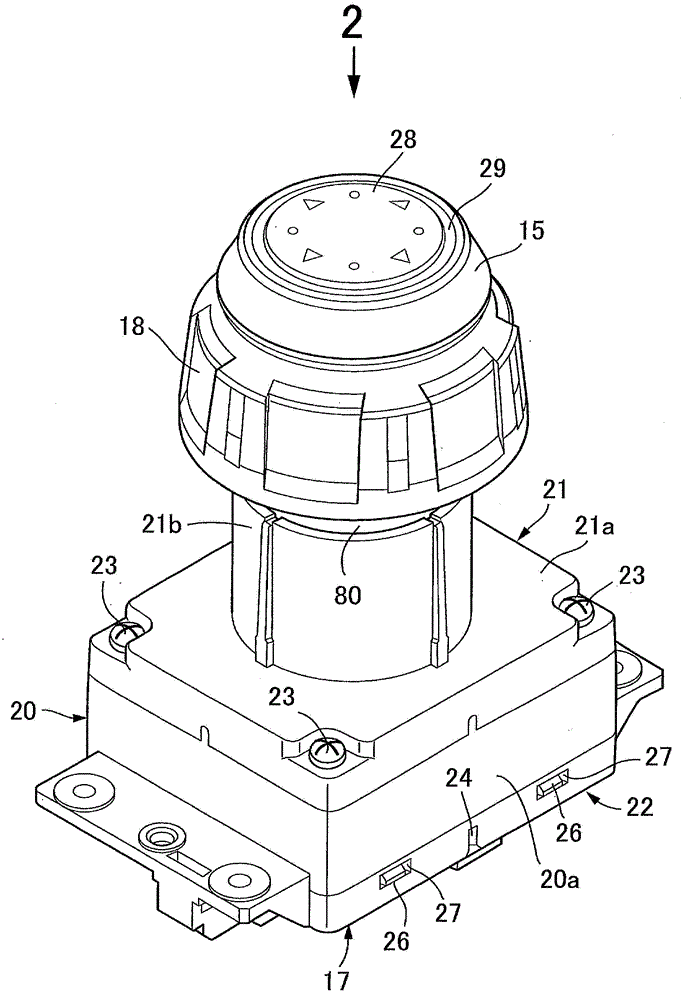
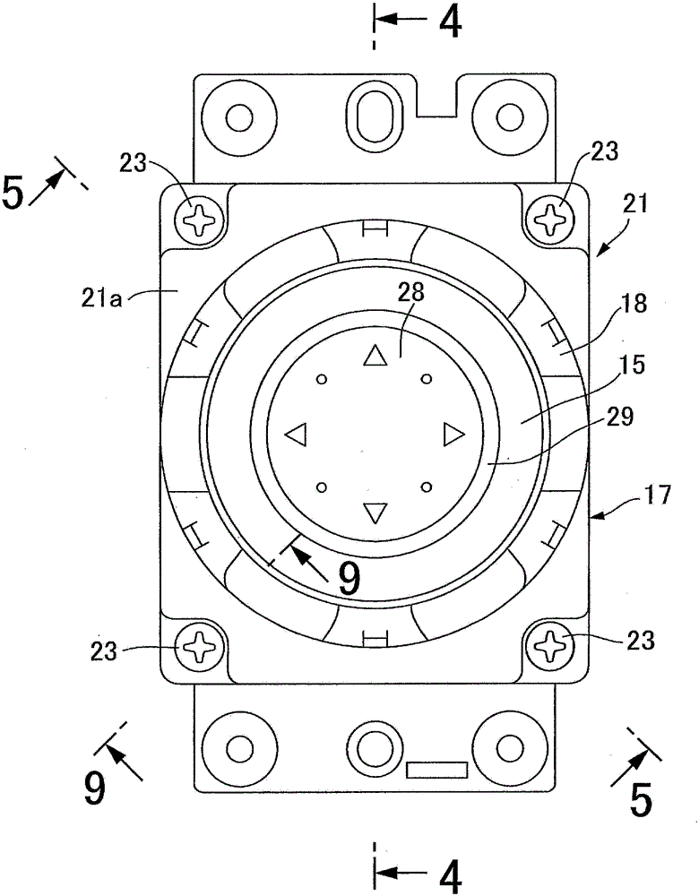
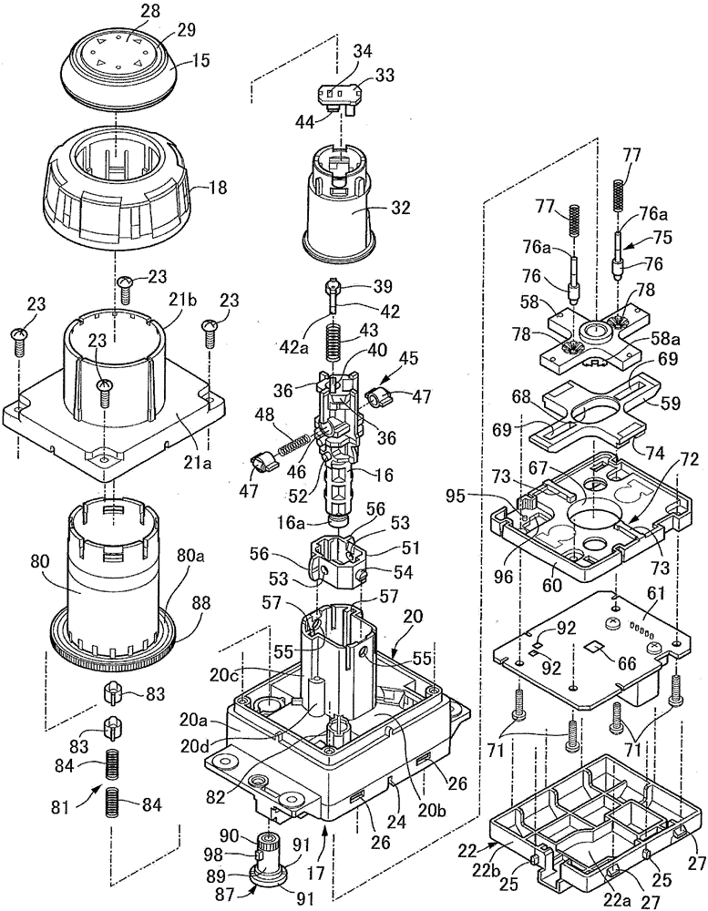
[0038] first in Figure 1 ~ Figure 3 Among them, the joystick device is, for example, a device for cursor operation on a screen of a car navigation system, and the joystick device includes: an operating handle 15; an operating shaft 16, one end of which is connected to the operating handle 15; a housing 17, It supports the operation shaft 16 and enables tilting movement of the operation shaft 16 ; and a toggle handle 18 formed to be rotatable about the axis of the operation shaft 16 and disposed adjacent to the operation handle 15 .

[0039] together with reference Figure 4 , the housing 17 includes: a housing main body 20; a first cover member 21, which is fastened to the housing main body 20 by a plurality of screw members 23, 23...; and a second cover member 22, which is connected with the first An opposite side of a cover member 21 is coupled to the hous...


PUM


Abstract

In a joystick device where a tilting operation direction of an operation shaft is detected based on positional change of a magnet relative to a magnetic sensor, the magnet being moved with tilting of the operation shaft, a slider (59) is arranged between a base (60) facing a board (61) fixed to a case (17) and a magnet holder (58) to which the operation shaft (16) is swingably coupled; the magnet holder (58) is joined to the slider (59) such that the slider (59) guides relative movement of the holder (58) in a first linear direction orthogonal to the axis of the operation shaft (16) but prevents relative movement of the holder (58) in a second linear direction orthogonal to the first direction; and a guide mechanism configured to guide movement of the slider (59) in the second direction is provided between the slider (59) and the base (60). This prevents variation in the detection accuracy by keeping constant a distance between the magnet and the sensor regardless of tilting of the shaft.

Description

technical field [0001] The present invention relates to a joystick device. The joystick device includes: an operating handle; an operating shaft, one end of which is connected to the operating handle; a shaft capable of tilting from a neutral position around a tilting center set on the axis of the operating shaft; a magnetic sensor provided on a substrate fixed to the case; and a magnet The operation shaft is formed to move according to the tilting movement of the operation shaft, and the magnet is arranged to face the magnetic sensor, and the joystick device detects the operation shaft based on a change in the relative position of the magnet with respect to the magnetic sensor. The direction of the tilt motion operation. Background technique [0002] For example, Patent Document 1 discloses a joystick device in which a magnet is provided at the other end of an operation shaft provided with an operation handle at one end so as to face a magnetic sensor provided on a substra...

Claims


Application Information

Patent Timeline
Patent Type & Authority Patents(China)
IPC IPC(8): G05G9/047
CPCG05G9/047G01D5/145G06F3/0338Y10T74/20201
Inventor 寺尾隆则中川晓伊东秀章
Owner TOYO DENSO CO LTD
Why Eureka
Try Eureka