Linear stroke transmission device of electric valve actuator
A technology of electric valve and transmission device, applied in the field of actuator transmission device and transmission device, can solve the problems of internal thread nut wear and tear, reduce adjustment accuracy, increase matching clearance, etc., so as to improve matching accuracy, reduce wear and improve wear resistance. sexual effect
Active Publication Date: 2010-12-01
ROTORK ACTUATOR
View PDF0 Cites 1 Cited by
- Summary
- Abstract
- Description
- Claims
- Application Information
AI Technical Summary
Problems solved by technology
The disadvantage is that the screw of the push rod and the inner threaded nut of the drive bushing cooperate with each other for transmission during use, and the hardness and wear resistance of the screw can be improved through the quenching process, while the copper nut of the drive bush is not easy to harden Therefore, in the process of cooperation between the two, the internal thread nut of the drive bushing is very easy to wear. After long-term use, the cooperation gap between the two increases, reducing the adjustment accuracy and shortening the service life of the product.
Method used
View moreImage
Smart ImageViewing Examples
Examples
Embodiment Construction
Login to View More PUM
 Abstract
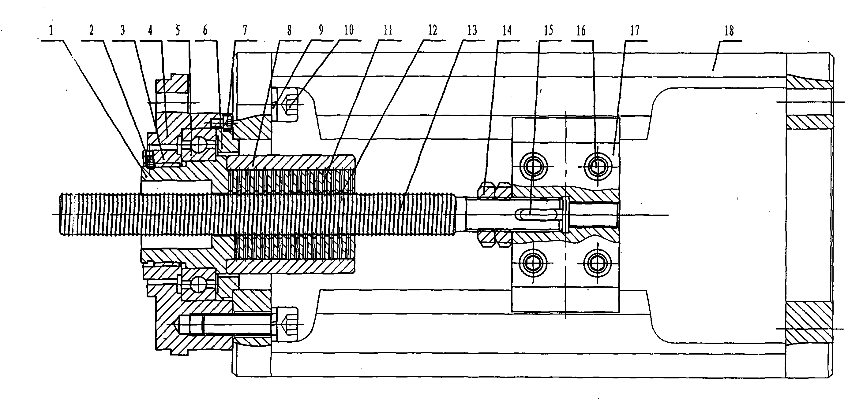
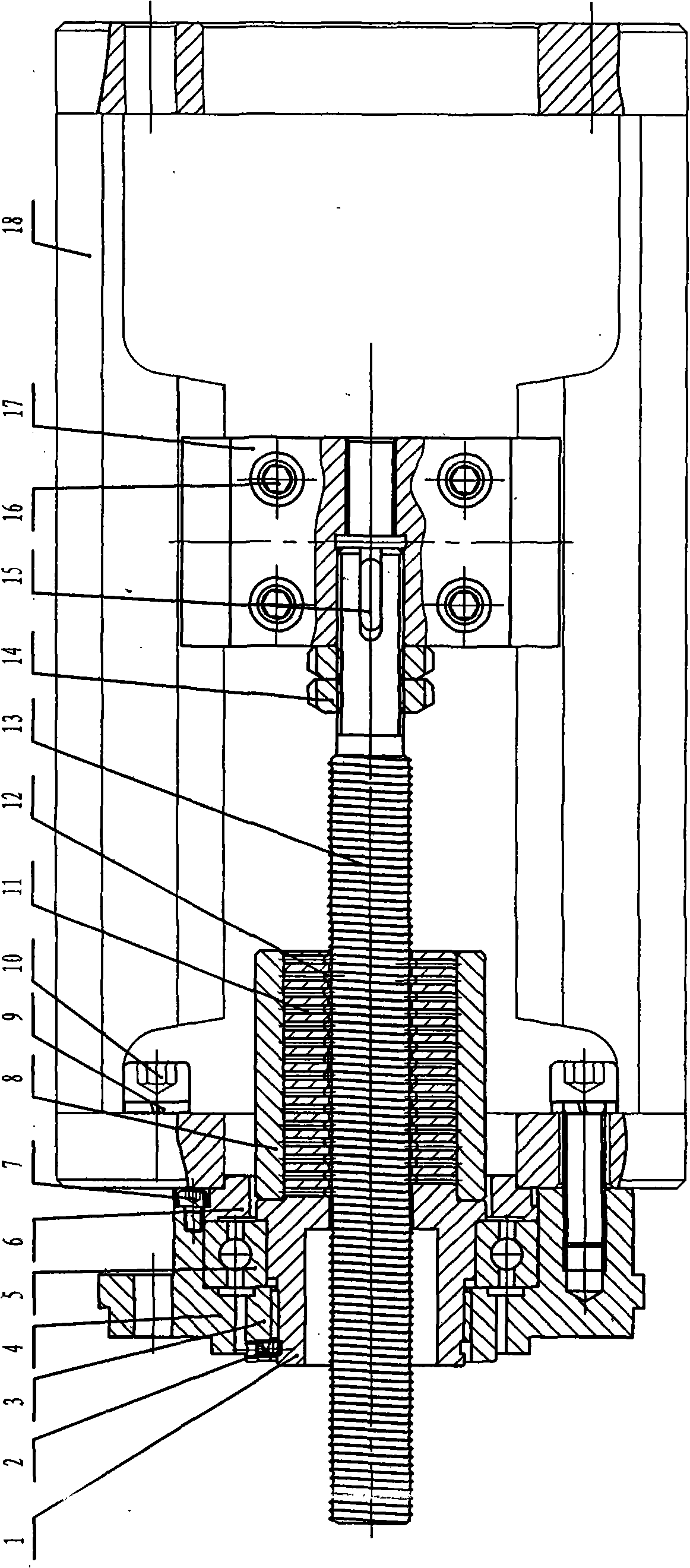
The invention relates to a linear stroke transmission device of an electric valve actuator, which comprises a thrust base, a bracket, a driving shaft housing and a thrust rod. One end of the thrust rod is provided with a screw rod, and the other end thereof is fixedly connected with a valve rod of a controlled valve by a plywood; the two sides of the plywood are embedded in the vertical groove ofthe bracket; as the screw rod of the thrust rod is provided with arc groove threads, the driving shaft housing is evenly provided with ball bearing holes along the spiral direction corresponding to the arc groove threads of the thrust rod, and ball bearings and needle rollers are arranged in the ball bearing holes; the ball bearings are provided with spherical circular arcs matched with the thrustrod arc groove threads; and the driving shaft housing outside the needle rollers is provided with a fixed housing. External threads of the thrust rod are matched the ball bearings in the driving shaft housing in a rolling way for transmission so as to reduce the friction and improve the fitting accuracy thereof; in addition, the transmission device has the advantages of stable and reliable accuracy control, and long product service life and the like, thus being applied to adjustment of the valve actuator.
Description
Linear drive for electric valve actuators technical field The invention relates to an actuator transmission device, in particular to a linear stroke transmission device of an electric valve actuator. The invention is applicable to the transmission device of the regulating valve actuator. Background technique The linear transmission device of the existing electric valve actuator generally includes a thrust base, a bracket, a drive bushing, and a push rod. Installed in the thrust base, the screw with external thread at one end of the push rod is connected with the internal thread nut of the drive bushing, the other end of the push rod is fixedly connected with the valve stem of the adjusted valve through the clamping plate, and the two sides of the clamping plate Embedded in the vertical groove of the bracket. When the thrust base and the drive bushing are rotated by the turntable of the motor output shaft of the electric valve actuator, due to the restriction of the plywo...
Claims
Login to View More Application Information
Patent Timeline
 Patent Type & Authority Patents(China)
IPC IPC(8): F16K31/50
Inventor 范陈云彭叔初金大刚
Owner ROTORK ACTUATOR
Features
- R&D
- Intellectual Property
- Life Sciences
- Materials
- Tech Scout
- Unparalleled Data Quality
- Higher Quality Content
- 60% Fewer Hallucinations
Learn More Browse by: Latest US Patents, China's latest patents, Technical Efficacy Thesaurus, Application Domain, Technology Topic, Popular Technical Reports.
© 2025 PatSnap. All rights reserved.Legal|Privacy policy|Modern Slavery Act Transparency Statement|Sitemap|About US| Contact US: help@patsnap.com


