Magnetic grab bucket

A grab and ferromagnetic technology, applied in the direction of magnets, magnetic objects, permanent magnets, etc., can solve the problems of not being able to automatically identify whether the workpiece has been received or the workpiece has been lost, and achieve the effect of simple structure and no inclination

Inactive Publication Date: 2009-10-28
TRUMPF WERKZEUGMASCHINEN GMBH & CO KG
View PDF1 Cites 7 Cited by
  • Summary
  • Abstract
  • Description
  • Claims
  • Application Information

AI Technical Summary

Problems solved by technology

The disadvantage of this magnetic grab is that it cannot automatically recognize whether a workpiece has been received or whether a workpiece has been lost during conveying

Method used


Image

  • Magnetic grab bucket
  • Magnetic grab bucket
  • Magnetic grab bucket

Examples


Embodiment Construction

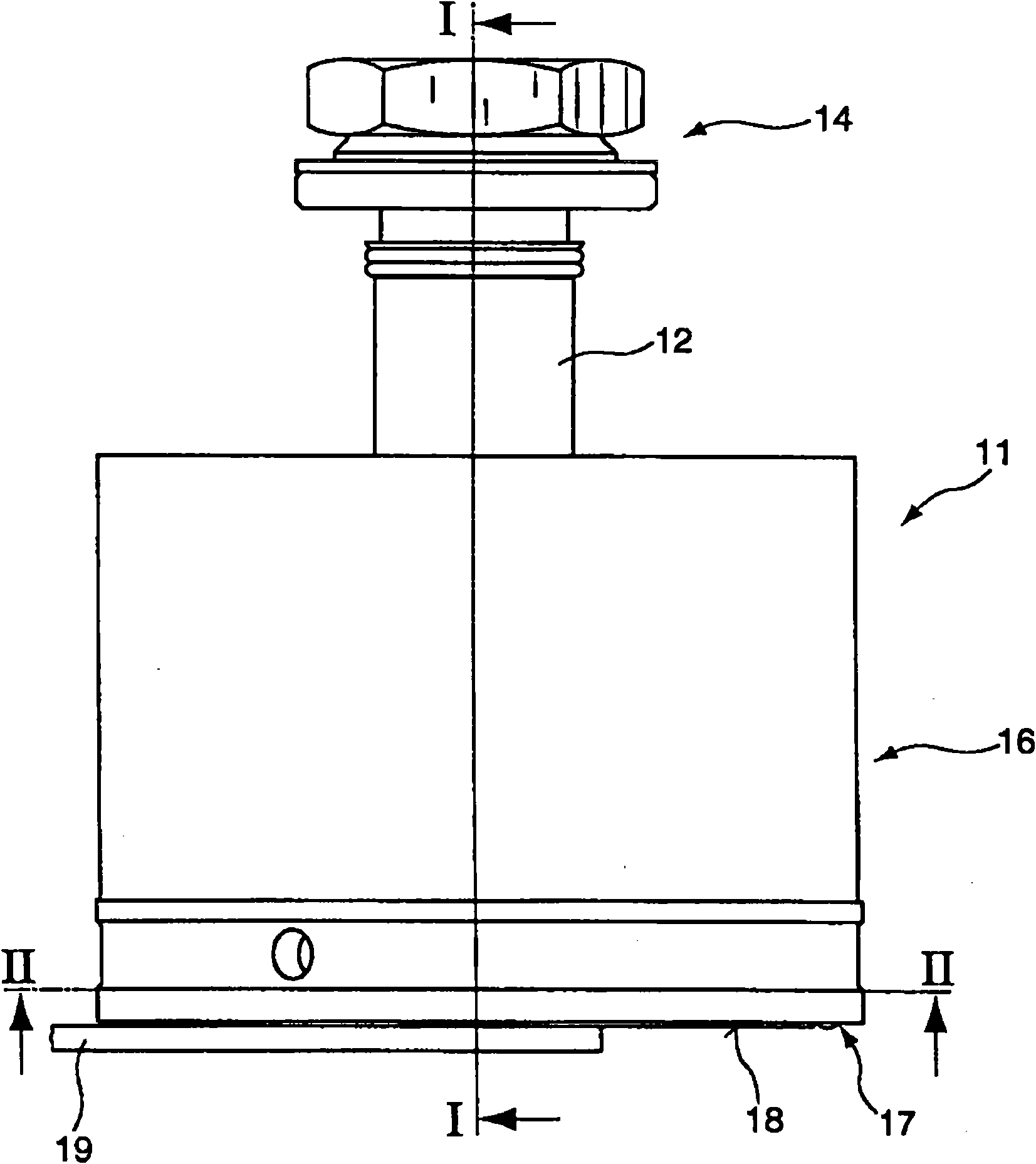
[0030] figure 1 A schematic side view of a magnetic grab 11 is shown having a neck 12 with fastening means 14 for fastening the magnetic grab to a robot arm or handling device. On the opposite side, a housing base 17 is provided on the cup-shaped housing 16 , which is screwed onto the housing 16 , for example. The housing base 17 has an end face 18 which is abutted by a gripped workpiece 19 , represented for example as a ferromagnetic plate.

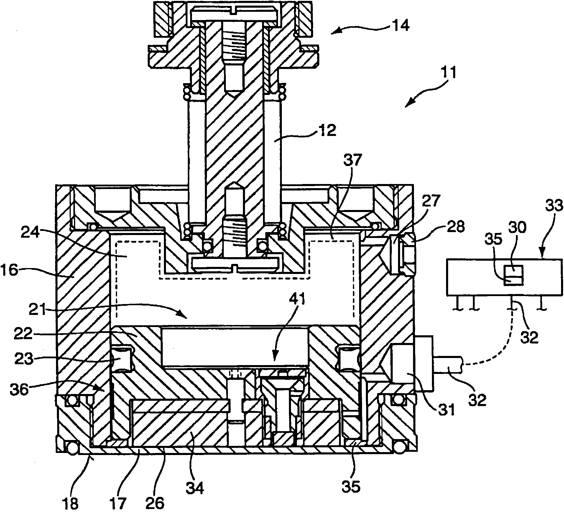
[0031] exist figure 2 is shown along the figure 1 Line I-I among is the sectional view that magnetic grab bucket 11 is done. In the housing 16 a magnetic piston 21 is guided so as to be movable up and down. The magnetic piston 21 comprises a guide ring 22 in which is arranged a seal 23 which separates an action chamber 24 present above the magnetic piston 21 from a piston chamber 26 present between the magnetic piston 21 and the housing base 17 . The volumes of these two chambers 24 , 26 are defined to be inversely proportional to...


PUM


Abstract

The invention relates to a magnetic grab bucket used for grabbing and carrying ferromagnetic workpieces. The magnetic grab bucket comprises a housing; a housing base is disposed on the housing; the housing base has an end face facing the workpiece to be grabbed; the magnetic grab bucket also comprises at least one magnetic piston disposed in the housing and at least one connecting piece equipped to the at least one magnetic piston. The connecting piece is used for connecting the working fluid used by the movable magnetic piston; thereby, the magnetic piston bears a first operating pressure, and is transmitted to the operating position, here, the magnetic piston is positioned on the housing base or near the housing base; and the magnetic piston is transmitted to the unused position under another operating pressure, here, the magnetic piston is positioned far from the housing base; wherein, at least one detection apparatus is disposed on or in the housing, used for detecting whether a workpiece exists on the end side of the housing.

Description

technical field [0001] The invention relates to a magnetic grab, which is used for grabbing and transporting ferromagnetic workpieces. The magnetic grab includes a shell on which a shell base is arranged. The shell base has a surface facing The end face of the workpiece to be grasped, the magnetic grab also includes at least one magnetic piston arranged in the housing and at least one connecting piece for the at least one magnetic piston, the connecting piece is used to connect the moving magnetic piston The working fluid used, whereby the magnetic piston is subjected to a first working pressure and delivered to the working position, where the magnetic piston is positioned on or near the housing base, and the magnetic piston is delivered to deactivation under another working pressure position where the magnetic piston is positioned away from the housing base. Background technique [0002] A magnetic grab of the aforementioned type is known from DE 19951703 A1. For gripping...

Claims


Application Information

Patent Timeline
Patent Type & Authority Applications(China)
IPC IPC(8): H01F7/02
CPCB66C1/04H01F7/0252H01F7/04
Inventor W·蒂尔
Owner TRUMPF WERKZEUGMASCHINEN GMBH & CO KG
Why Eureka
Try Eureka