

Variable capacitor and electronic device
一种电容器、可变的技术,应用在可变电容器、电压可变的电容器、电容器等方向
- Summary
- Abstract
- Description
- Claims
- Application Information
AI Technical Summary
Problems solved by technology
Method used
Image

Examples
no. 1 example
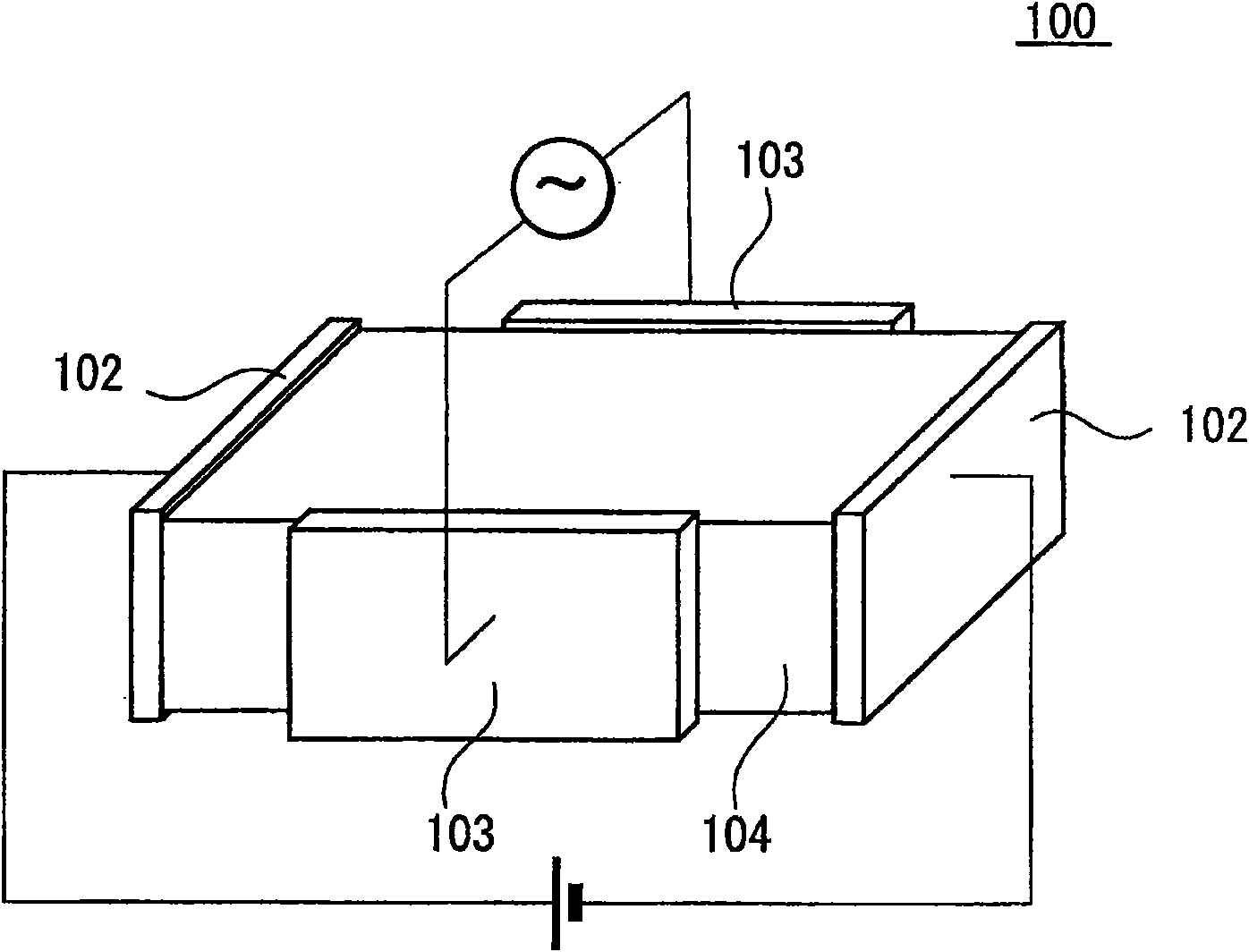
[0037] Figure 3A and 3B They are a schematic perspective view and a cross-sectional configuration view of the variable capacitor according to the first embodiment of the present invention, respectively. The variable capacitor 1 according to the first embodiment of the present invention includes a dielectric layer 4 formed in a rectangular parallelepiped shape, the four faces of which each have four terminals. exist Figure 3A and 3B Among them, the x-axis, y-axis, and z-axis respectively represent the horizontal direction from left to right, the vertical direction from bottom to top, and the depth direction from front to back of the variable capacitor 1 shown in the plane of the drawing.
[0038] Examples of materials for the dielectric layer 4 include ionically polarized and electronically polarized ferroelectric materials. Ionically polarized ferroelectric materials are formed from ionic crystal materials and are electrically polarized by atomic displacement between pos...
no. 2 example
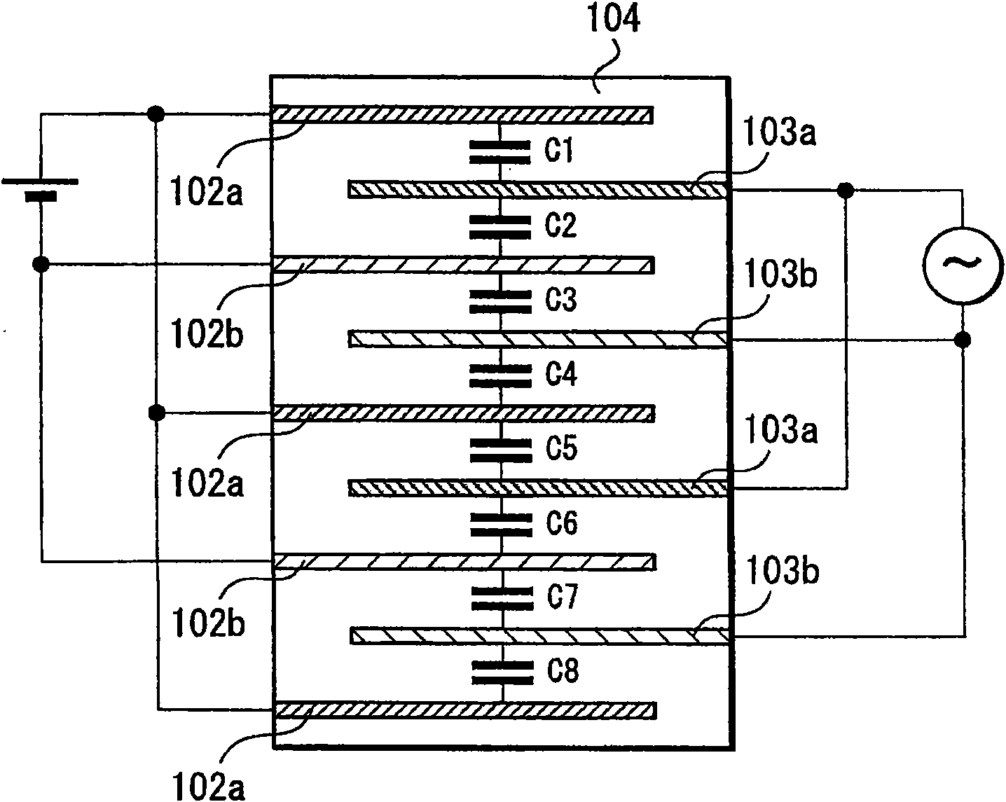
[0052] Figure 6A and 6B It is a schematic perspective view of a variable capacitor according to a second embodiment of the present invention and a cross-sectional configuration diagram thereof. exist Figure 6A , 6B, the x-axis, y-axis and z-axis respectively represent the horizontal direction from left to right, the vertical direction from bottom to top, and the depth direction from front to back of the variable capacitor 12 shown in the plane of the drawing. exist Figure 6A and 6B in, right and Figure 3A and 3B Corresponding elements are given the same reference numerals, and repeated descriptions thereof are omitted.
[0053] The variable capacitor 12 according to the second embodiment includes a dielectric layer 4 having a plurality of internal control electrodes 13 a , 13 b connected to the control terminal 2 . The internal control electrodes 13a, 13b are formed in a flat plate shape extending in the x·z surface direction, and six layers thereof are provided in ...
no. 3 example
[0063] Figure 9A and 9B A schematic perspective view of a variable capacitor according to a third embodiment of the present invention and a cross-sectional configuration diagram thereof. exist Figure 9A and 9B Among them, the x-axis, y-axis and z-axis respectively represent the horizontal direction from left to right, the vertical direction from bottom to top, and the depth direction from front to back of the variable capacitor 17 shown in the plane of the drawing.
[0064] exist Figure 9A and 9B in, right and Figure 3A and 3B Corresponding elements are given the same reference numerals, and repeated descriptions thereof are omitted.
[0065] The variable capacitor 17 according to the third embodiment comprises a dielectric layer 4 with two internal control electrodes 15 , 16 connected to the control terminal 2 . The inner control electrode 16 is connected to the first control terminal 2a, and the inner control electrode 15 is connected to the second control termin...
PUM
 Abstract
Description
Claims
Application Information