Passive orthopaedic aid in the form of a foot prosthetic or orthotic

An auxiliary device, passive technology, used in prosthesis, medical science, non-surgical orthopedic surgery, etc.

Active Publication Date: 2009-11-04
OTTO BOCK HEALTHCARE IP GMBH & CO KG
View PDF6 Cites 5 Cited by
  • Summary
  • Abstract
  • Description
  • Claims
  • Application Information

AI Technical Summary

Problems solved by technology

[0005] The problem arising from the prior art is that although the controllers of passive foot prostheses or foot orthos

Method used


Image

  • Passive orthopaedic aid in the form of a foot prosthetic or orthotic
  • Passive orthopaedic aid in the form of a foot prosthetic or orthotic
  • Passive orthopaedic aid in the form of a foot prosthetic or orthotic

Examples


Embodiment Construction

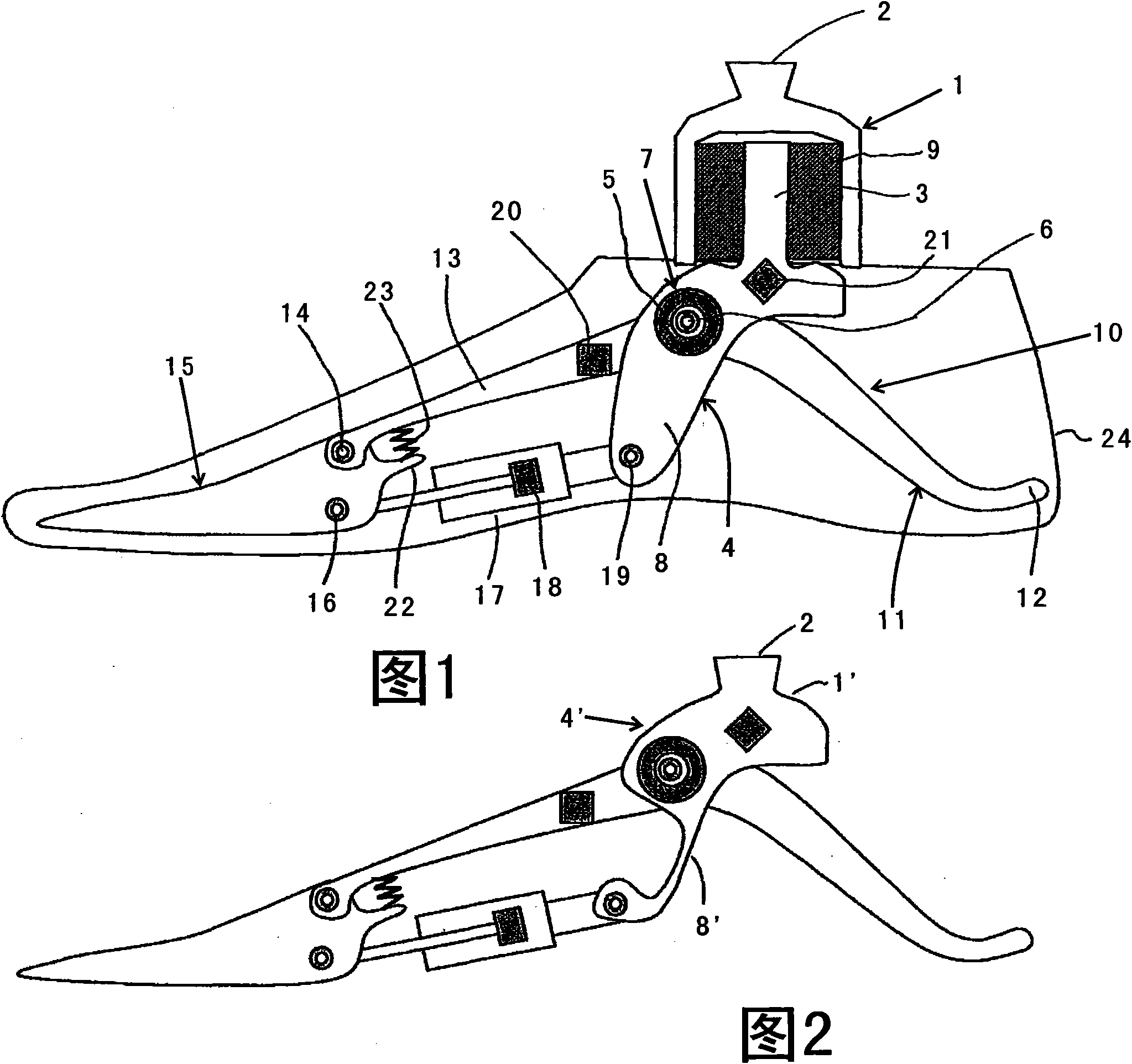
[0024] exist figure 1 In the embodiment shown in , the fixing element 1 is configured with an alignment protrusion 2 in the form of an inverted frustum of a pyramid with four slopes. The fastening part 1 forms a pot which is open at the bottom, into which the upwardly protruding web 3 of the double-arm lever 4 protrudes. The double-arm lever is rotatable about the swivel joint 5 , the swivel axis 6 of which at the same time forms the axis of the ankle joint of the artificial foot. The swivel hinge 5 is provided with an angle sensor 7 . The double-arm lever 4 has a rigid downwardly projecting projection 8 .

[0025] In the downwardly open pot of the fastening part 1, the intermediate space formed by the web 3 is filled with a relatively hard elastic material 9, whereby the movement of the fastening part 1 is only slightly damped and transmitted to the contact of the double-arm lever 4 Tablet 3 movement. Thus, the protrusion 8 follows the movement of the fixture 1 , but is s...


PUM


Abstract

The invention relates to a passive orthopedic aid, which compirses a first part which is connected to a second part in a rotatable manner via a swivel joint, with a sensor arrangement for measuring parameters that provide indications of instantaneous operation requirements of the aid, with a control means which is connected to the control arrangement and is used to determine operation requirements and to generate corresponding control signals, with a controllable hydraulic damping arrangement with which a movement resistance acting on the rotation movement between the first part and the second part can be modified, and with a control means which converts the control signals of the processor arrangement and is used to control the damping arrangement. The damping arrangement is a dual-action hydraulic cylinder with two hydraulic chambers separated from each other by a piston, and in that the hydraulic chambers are connected via two connection lines which permit a flow of the hydraulic fluid only in mutually opposite directions and whose flow resistances can be adjusted by the control separately and via their own adjustment means each, in that the processor arrangement is configured to determine a current neutral point position from the measured parameters of the sensor arrangement, and in that the control signals for the flow resistances in the two connection lines are generated with respect to the neutral point position.

Description

technical field [0001] The invention relates to a passive orthopedic aid in the form of a foot prosthesis or a foot orthosis, comprising: a first part rotatably connected to a second part via a rotary hinge; a sensor device for measuring parameters allowing to infer the transient usage requirements of the auxiliary device; a processor device for determining the usage requirements and generating corresponding control signals; a controllable hydraulic damping device, through which the hydraulic damping means for varying motion resistance to rotational movement between the first member and the second member; and a controller for converting a control signal from the processor means for controlling the damping means. Background technique [0002] Such orthopedic aids are known in particular as foot prostheses. The rotary hinge is usually an ankle joint that connects the link for the lower leg prosthesis to the foot piece. [0003] In the foot prosthesis known from US 2005 / 01977...

Claims


Application Information

Patent Timeline
IPC IPC(8): A61F2/66
CPCA61F2/6607A61F2002/5033A61F2002/7645A61F2002/745A61F2005/0141A61F2005/0158A61F2002/7625A61F2002/74A61F2002/5035A61F2002/6818A61F2002/5006A61F2/68A61F2005/0169A61F2002/748A61F2002/5038A61F2002/6854A61F2005/0144A61F2/66A61F2/70A61F5/0127A61F2/74A61F2/748A61F2002/5072A61F2002/704A61F2002/764A61F2005/0179
Inventor L·莫斯勒R·帕夫利克J·舍尔格S·卡尔滕博恩S·扎林G·施奈德
Owner OTTO BOCK HEALTHCARE IP GMBH & CO KG
Why Eureka
Try Eureka