
Doctor blade system

A squeegee and ink technology, used in printing, printing machines, general parts of printing machinery, etc., can solve problems such as frequent maintenance, and achieve the effect of precise positioning

Inactive Publication Date: 2009-11-04
KOENIG & BAUER AG
View PDF1 Cites 23 Cited by
  • Summary
  • Abstract
  • Description
  • Claims
  • Application Information

AI Technical Summary

Problems solved by technology

Therefore, more frequent maintenance is often required

Method used


Image

  • Doctor blade system
  • Doctor blade system
  • Doctor blade system

Examples


Embodiment Construction

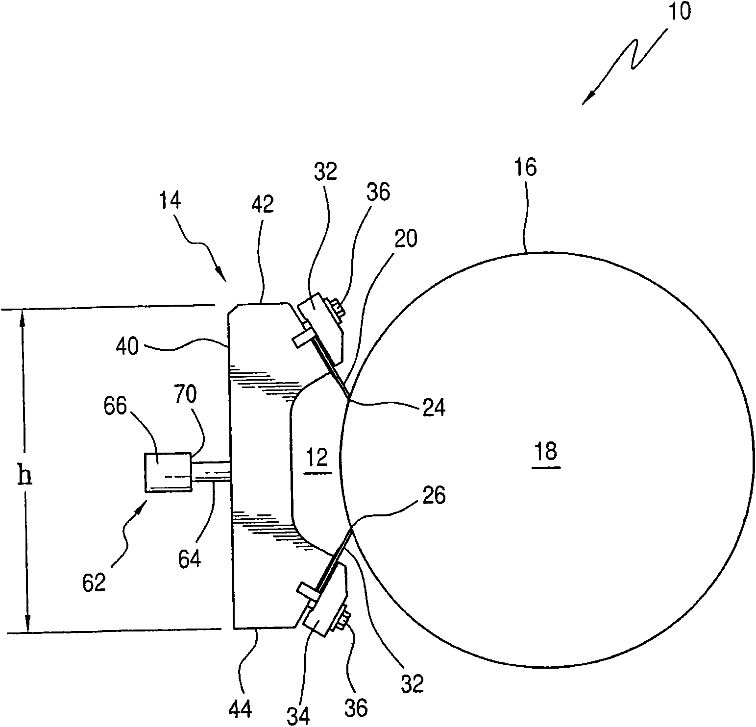
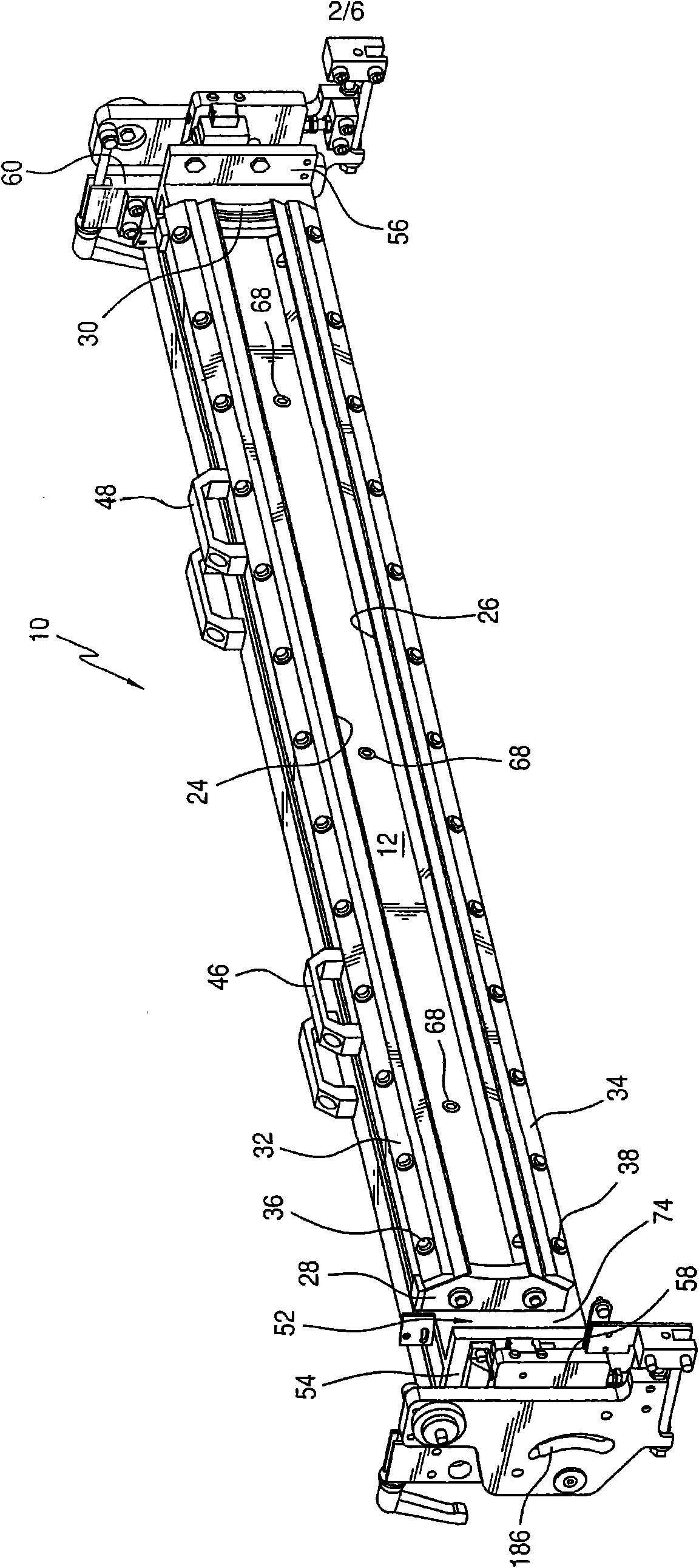
[0038] First refer to figure 1 and combine figure 2 , a preferred embodiment of the doctor blade system according to the invention, indicated overall at 10 , can be seen. It will be appreciated that the doctor blade system, generally indicated at 10, is intended primarily for use in flexographic printing systems or in other commonly known printing systems. In such a system, printing ink is supplied to an ink reservoir 12 within a doctor blade chamber, indicated generally at 14 . Those inks are then transferred to the surface 16 of an ink roller, such as an anilox roller 18 .

[0039] As is well known in the art, the doctor blade chamber, indicated generally at 14, includes an active doctor blade 20 and a closed doctor blade 22, the outer edges 24, 26 of the active doctor blade 20 and the closed doctor blade 22 The surfaces 16 of the anilox rollers 18 are respectively engaged. Such as figure 2 Appropriate end plates 28 and 30 cooperate with the active squeegee 20 and the...


PUM


Abstract

The present invention discloses a doctor blade system which utilizes a lightweight doctor blade chamber to apply ink to an inking roller. The doctor blade chamber is removably positioned on a support plate which is, in turn, carried by linear guides on pivotable end plates. A rigid box beam is also attached to the end plates and is spaced from the support plate. A plurality of membrane cylinders are mounted on the rigid box beam and engage a surface of the support plate opposite to the surface that supports the doctor blade chamber. Through the application of suitable force, the support plate and its supported doctor blade chamber can be moved, by sliding motion on the linear slides, into uniform engagement with the surface of the ink roller. The system uses pivotable end plates which are supported by exterior plates that are, in turn, pivotably supported by press side frames. The chamber doctor blade and its support plate and box beam can be moved into several different positions, with respect to the cooperating ink roller, to facilitate doctor blade chamber cleaning or replacement or ink roller replacement.

Description

technical field [0001] The present invention generally relates to a doctor blade system. More specifically, the present invention relates to a doctor blade system for a rotary press. Most particularly, the present invention relates to a doctor blade system for a flexographic printing press. The doctor blade system includes a lightweight material doctor blade chamber. A full length support plate supports the doctor blade chamber. In the axial direction of a cooperating anilox roller, the support plate is biased across its width by a plurality of film rollers. Those film rolls are fixed to rigid beams. The result is a lightweight squeegee blade that is not subject to bending and deformation, which were so prevalent in previous installations. Background technique [0002] As is known, in the field of rotary presses it is common to provide inkjet units equipped with chamber-type doctor blade assemblies. Such a chambered doctor blade assembly would include an elongated doct...

Claims


Application Information

Patent Timeline
Patent Type & Authority Applications(China)
IPC IPC(8): B41F31/04
CPCB41F31/027
Inventor 埃瓦尔德·勒特莱因赫尔穆特·施密特
Owner KOENIG & BAUER AG
Learn More