
Motor decelerating mechanism of electric bicycle

A technology for electric bicycles and deceleration mechanisms, which is applied to vehicle gearboxes, vehicle components, wheel transmissions, etc., can solve the problems of unsightly appearance and increased volume, and achieve the effect of small volume and large deceleration ratio

Inactive Publication Date: 2009-11-04
刘运柳
View PDF0 Cites 2 Cited by
  • Summary
  • Abstract
  • Description
  • Claims
  • Application Information

AI Technical Summary

Problems solved by technology

[0002] The speed of the common motor of the existing electric bicycle is about 3600-4200 revolutions per minute, and it must be decelerated to about 300 revolutions per minute to ride; After the small gear on the auxiliary shaft drives the large gear on the auxiliary shaft to decelerate, the small gear on the auxiliary shaft drives the large gear on the wheel shaft for a second deceleration and then outputs; because the side of the wheel shaft is very large, many companies are To increase the reduction ratio, the motor is made into a semi-shaft form and placed on the side of the rim, which obviously increases the volume and is not beautiful

Method used


Image

  • Motor decelerating mechanism of electric bicycle
  • Motor decelerating mechanism of electric bicycle
  • Motor decelerating mechanism of electric bicycle

Examples


Embodiment Construction

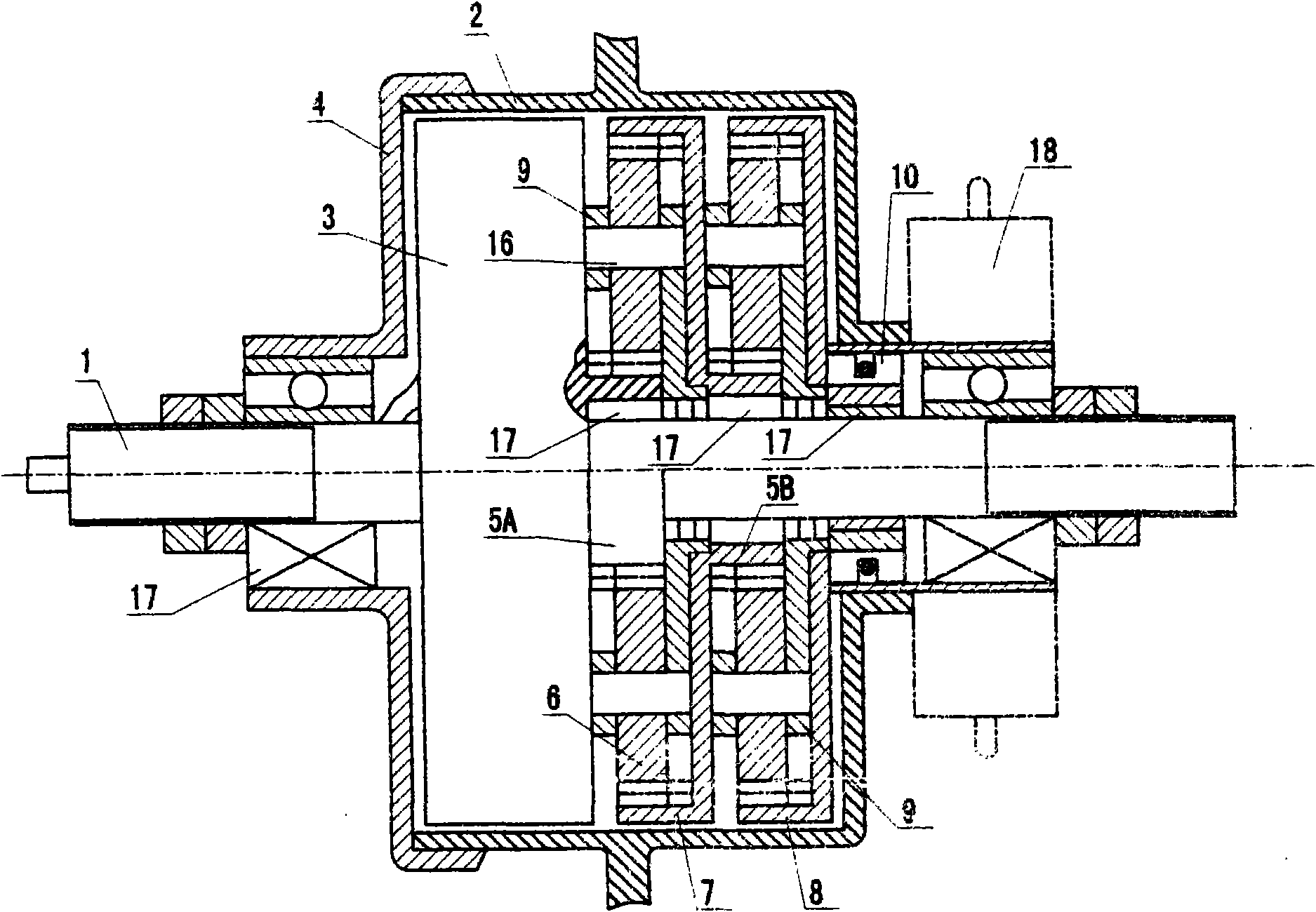
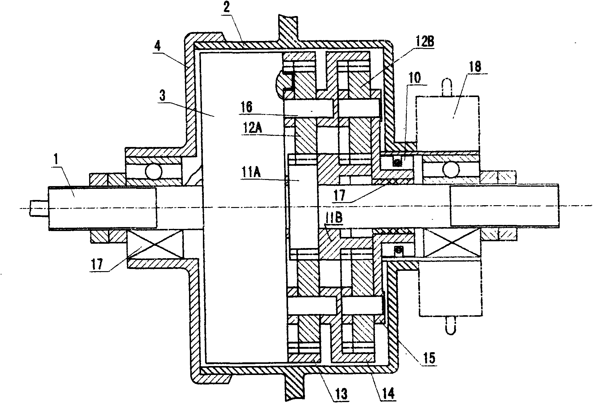
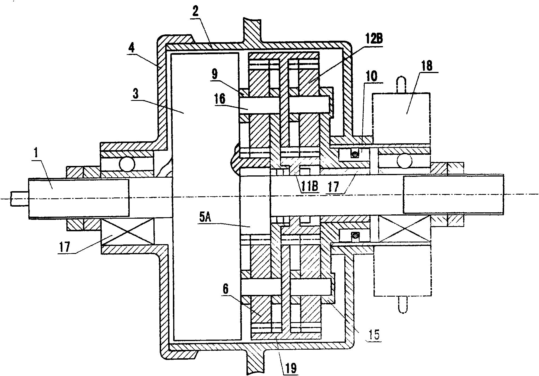
[0017] Describe in detail below in conjunction with accompanying drawing, comprise wheel shaft 1, housing 2, motor 3, cover 4, the 1st stage driving gear 5A, the 2nd stage driving gear 5B, intermediate wheel 6, the first stage with driving gear among the accompanying drawings Stage internal gear 7, second stage internal gear equipped with ratchet or round pin 8, intermediate wheel mount 9, pawl or round pin 10, first stage sun gear 11A, second stage sun gear 11B, planetary gear 12A , planetary gear 12B, internal gear 13 connected with motor rotor, internal gear 14 equipped with planetary gear, planetary gear mount 15 equipped with ratchet or garden pin, intermediate wheel or planetary gear shaft 16, bearing 17, flywheel 18, double internal gear 19, return spring 20.

[0018] figure 1 It is a two-stage reduction mechanism diagram in which the driving gear is installed on the wheel shaft to reduce the internal gear through the intermediate gear. The driving gear 5A connected wi...


PUM


Abstract

A motor decelerating mechanism of an electric bicycle comprises a motor, a wheel shaft, a shell and a secondary decelerating mechanism such as a drive gear or a sun gear, an intermediate gear or a planetary gear, an internal gear, and the like. The way of the deceleration is as follows: a rotating speed output by the drive gear is transmitted to the internal gear through the intermediate gear so as to enable the intermediate gear to perform deceleration movement; the internal gear drives to encircle the sun gear through the planetary gear to do the deceleration movement; and two mechanisms are combined to form the decelerating mechanism with the intermediate gear and the planetary gear. The several mechanisms have large deceleration proportions and small volumes.

Description

technical field [0001] The invention relates to a speed reduction mechanism of an electric bicycle motor Background technique [0002] The speed of the common motor of the existing electric bicycle is about 3600-4200 revolutions per minute, and it must be decelerated to about 300 revolutions per minute to ride; After the small gear on the auxiliary shaft drives the large gear on the auxiliary shaft to decelerate, the small gear on the auxiliary shaft drives the large gear on the wheel shaft for a second deceleration and then outputs; because the side of the wheel shaft is very large, many companies are To increase the reduction ratio, the motor is made into a semi-shaft form and placed on the side of the rim, which obviously increases the volume and is not beautiful. Contents of the invention [0003] The present invention is to improve the existing motor reduction mechanism. The wheel shaft on one side of the motor is connected with the motor rotor, and a gear is install...

Claims


Application Information

Patent Timeline
IPC IPC(8): B62M11/14
Inventor 刘运柳
Owner 刘运柳
Learn More