Reducer with less tooth difference

A reducer and less tooth difference technology, which is applied in the direction of gear transmission, components with teeth, belt/chain/gear, etc., can solve the problems of instability, high noise, short service life, etc., and achieve the problem of overweight, The effect of large torque transmission and compact structure

Inactive Publication Date: 2011-10-19
宿孝廷
View PDF7 Cites 12 Cited by
  • Summary
  • Abstract
  • Description
  • Claims
  • Application Information

AI Technical Summary

Problems solved by technology

[0004] The above patents respectively use a pair of bevel gears to realize the speed change, and use the other pair of bevel gears to output the speed change, which requires high meshing precision of the gear pair. There is a lot of vibration, unstable, loud noise during operation, easy to damage, short service life and poor reliability

Method used


Image

  • Reducer with less tooth difference
  • Reducer with less tooth difference
  • Reducer with less tooth difference

Examples


Embodiment Construction

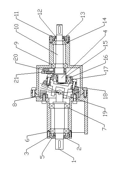
[0026] Examples such as figure 1 As shown, a reducer with few tooth differences includes a box, an input shaft 10 and an output shaft 1, a universal coupling 19 is provided between the input shaft 10 and the output shaft 1, and the end of the input shaft 10 in the box is provided with There is an eccentric shaft head 4, a needle bearing 15 is fixed on the eccentric shaft head 4, a joint bearing 16 is arranged on the needle bearing 15, a bearing sleeve 17 is arranged on the joint bearing 16, and the connection between the bearing sleeve 17 and the universal coupling 19 The input end is fixedly connected, the input end of the universal coupling 19 is fixedly connected with a swing bevel gear 18, and the box on the side of the output shaft 1 is fixed with a fixed bevel gear 8, the teeth of the swing bevel gear 18 and the fixed bevel gear 8 The shape is distributed along the circumference, and the fixed bevel gear 8 is meshed with the swing bevel gear 18. The shaft angle when the ...


PUM


Abstract

The invention relates to a reducer with less tooth difference, comprising a box body, an input shaft and an output shaft, wherein a universal coupler is arranged between the input shaft and the output shaft; an eccentric shaft head is arranged at the end part of the input shaft and is provided with an oscillating bearing; the oscillating bearing is provided with a bearing bush; the input end of the universal coupler is fixedly connected with the bearing bush and a swinging bevel gear; the box body is fixed with a fixed bevel gear meshed with the swinging bevel gear; and the input end of the universal coupler is connected with an output shaft; teeth of the fixed bevel gear are more than teeth of the swinging bevel gear, the structure is compact, and when fixed bevel gear is meshed with theswinging bevel gear, a crossed axis angle ranges from 150 degrees to 178 degrees. Due to the arrangement, the number of the meshed teeth of the fixed bevel gear and the swinging bevel gear are more than those of traditional hear transmission, so that transmitted torque is large, and speed change with the large reduction ratio and large load can be realized; and due to the arrangement of a balancedevice, the problem of laterality when the swinging bevel gear rotates can be solved, so that a reduction gear can move more stably and has low noise.

Description

technical field [0001] The invention relates to a speed reducer, in particular to a speed reducer with small tooth difference, which belongs to the technical field of machinery. Background technique [0002] At present, there has been a bevel gear one-tooth difference reducer, such as the patent number 022062939, the name is: double bevel gear less tooth difference reducer, the technical solution adopted is a pair of conical gears with a tooth difference of 1 meshing, one of which is a plane Or the flat-top gear (fixed toothed disc) is fixed to the box, and the other gear (swing toothed disc) is engaged in rolling engagement on the fixed toothed disc; since the difference in the number of teeth between the two wheels is l, the swinging toothed disc will rotate around itself after rolling and meshing for one week. The axis rotates through one tooth in the opposite direction; another pair of bevel gears with the same number of teeth meshes, one of them (the small toothed disc)...

Claims


Application Information

Patent Timeline
Patent Type & Authority Applications(China)
IPC IPC(8): F16H1/14F16H57/02F16H57/00
Inventor 宿孝廷
Owner 宿孝廷
Why Eureka
Try Eureka